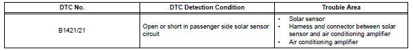
Toyota RAV4 (XA40) 2013-2018 Service Manual: Solar sensor circuit (passenger side)
![]()
Description
The solar sensor, which is installed on the upper side of the instrument panel, detects sunlight and controls the air conditioning auto mode. The output voltage from the solar sensor varies in accordance with the amount of sunlight. When the sunlight increases, the output voltage increases. As the sunlight decreases, the output voltage decreases.
The air conditioning amplifier detects changes in the output voltage from the solar sensor.
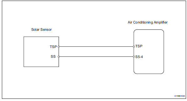
Wiring diagram
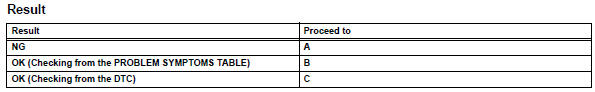
Inspection procedure
- Read value of intelligent tester (solar sens-p)
- Connect the intelligent tester (with can vim) to the dlc3.
- Turn the ignition switch on and turn the intelligent tester main switch on.
- Select the item below in the data list, and read the value displayed on the intelligent tester.
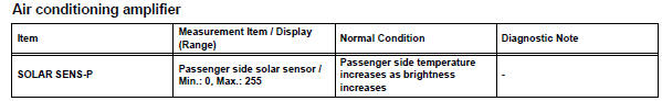
Ok: the display is as specified in the normal condition column.

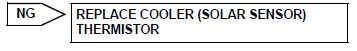
- Inspect cooler (solar sensor) thermistor
- Remove the solar sensor.
- Measure the resistance of the sensor.
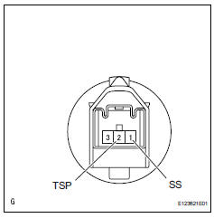
- Connect the ohmmeter's positive (+) lead to terminal 1 and the negative (-) lead to terminal 2 of the solar sensor.
Standard resistance 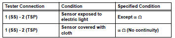
Notice:
The connection procedure for using a digital tester such as an electrical tester is shown above. When using an analog tester, connect the positive (+) lead to terminal 2 and the negative (-) lead to terminal 1 of the solar sensor.
Hint:
- As the inspection light is moved away from the sensor, the voltage decreases.
- Use an incandescent light for the inspection. Position it about 30 cm (11.8 In.) From the solar sensor.

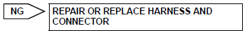
- Check wire harness (solar sensor - air conditioning amplifier)
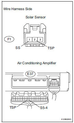
- Disconnect the f1 sensor connector.
- Disconnect the e37 amplifier connector.
- Measure the resistance of the wire harness side connectors.
Standard resistance 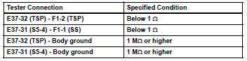

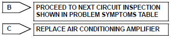
Replace air conditioning amplifier
 Evaporator temperature sensor circuit
Description
The no. 1 Cooler thermistor (evaporator temperature sensor) is installed on
the evaporator in the air
conditioning unit to detect the temperature of the cooled air that has passed ...
 Compressor lock sensor circuit
Description
This sensor sends 1 pulse per engine revolution to the air conditioning
amplifier. If the ratio of the
compressor speed divided by the engine speed is smaller than a predetermined ...
Other materials:
Installation
Install water pump assembly
Remove any old seal packing material from the
contact surface.
Apply a continuous line of seal packing as shown in
the illustration.
Seal packing:
toyota genuine seal parking black, three
bond 1207b or equivalent
Standard seal diameter:
2.2 To 2. ...
Ecm / pcm internal engine off timer performance
Dtc summary
Description
To ensure the accuracy of the evap (evaporative emission) monitor values, the
soak timer, which is built
into the ecm, measures 5 hours (+-15 minutes) from when the ignition switch is
turned off, before the
monitor is run. This allows the fuel to cool down, wh ...
Adjusting the open position
of the back door
(vehicles with power back
door)
The open position of the power
back door can be adjusted.
1. Stop the back door in the
desirable position.
2. Press and hold the power
back door switch on the back
door for approximately 2 seconds.
When the settings are completed,
the buzzer sounds 4 times.
When opening the back door the
next time ...
