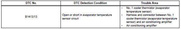
Toyota RAV4 (XA40) 2013-2018 Service Manual: Evaporator temperature sensor circuit
![]()
Description
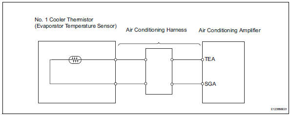
The no. 1 Cooler thermistor (evaporator temperature sensor) is installed on the evaporator in the air conditioning unit to detect the temperature of the cooled air that has passed through the evaporator and to control the air conditioner. It sends signals to the air conditioning amplifier. The signals change in accordance with the resistance of the no. 1 Cooler thermistor (evaporator temperature sensor). As the temperature decreases, the resistance increases. As the temperature increases, the resistance decreases. The air conditioning amplifier applies a voltage (5 v) to the no. 1 Cooler thermistor (evaporator temperature sensor) and reads voltage changes as changes in the resistance of the no. 1 Cooler thermistor (evaporator temperature sensor). This sensor is used for frost prevention.
Wiring diagram
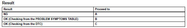
Inspection procedure
- Read value of intelligent tester (evap fin temp)
- Connect the intelligent tester (with can vim) to the dlc3.
- Turn the ignition switch on and turn the intelligent tester main switch on.
- Select the item below in the data list, and read the value displayed on the intelligent tester.
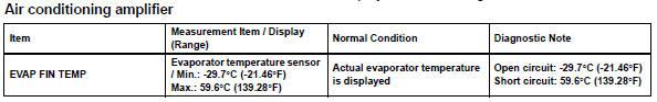
Ok: the display is as specified in the normal condition column.

- Inspect no. 1 Cooler thermistor (evaporator temperature sensor)
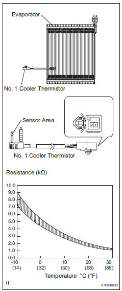
- Remove the no. 1 Cooler thermistor.
- Measure the resistance of the thermistor.
Standard resistance 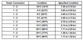
Notice:
- Touching the thermistor even slightly may change the resistance value. Be sure to hold the connector of the thermistor.
- When measuring, the thermistor temperature must be the same as the ambient temperature.
Hint:
As the temperature increases, the resistance decreases (see the graph).


Replace air conditioning harness assembly
 Ambient temperature sensor circuit
Description
The ambient temperature sensor is installed in the front part of the
condenser to detect the ambient
temperature and control the air conditioner. The sensor is connected to the
c ...
 Solar sensor circuit (passenger side)
Description
The solar sensor, which is installed on the upper side of the instrument
panel, detects sunlight and
controls the air conditioning auto mode. The output voltage from the solar
se ...
Other materials:
Slip indicator light does not come on
Description
Refer to the description of "slip indicator light remains on" (see page
bc-152).
Wiring diagram
Refer to the slip indicator light circuit (see page bc-152).
Inspection procedure
Notice:
When replacing the abs and traction actuator, perform the zero point
calibration ( ...
Data list / active test
Read data list
Hint:
Using the intelligent tester's data list allows switch,
sensor, actuator and other item values to be read without
out removing any parts. Reading the data list early in
troubleshooting is one way to save time.
Connect the intelligent tester (with can vim) to the
...
Coolant thermostat (coolant temperature below thermostat regulating
temperature)
Hint:
This dtc relates to the thermostat.
Description
This dtc is set when the engine coolant temperature (ect) does not reach 75°c
(167°f) despite
sufficient engine warm-up time having elapsed.
Monitor description
The ecm estimates the ect based on the starting temperature, en ...
