Toyota RAV4 (XA40) 2013-2018 Service Manual: Compressor lock sensor circuit
![]()
Description
This sensor sends 1 pulse per engine revolution to the air conditioning amplifier. If the ratio of the compressor speed divided by the engine speed is smaller than a predetermined value, the air conditioning amplifier turns the compressor off, and the indicator blinks at approximately 1 second intervals.

Wiring diagram

Inspection procedure
- Check air conditioning amplifier (lock signal)

- Remove the air conditioning amplifier with its connectors still connected.
- Check the waveform of the amplifier connector.
Ok:
waveform is as shown in the illustration.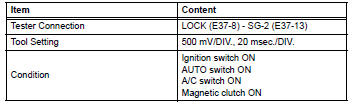


- Inspect compressor lock sensor

- Disconnect the b47 compressor lock sensor connector.
- Measure the resistance of the sensor.
Standard resistance


- Check wire harness (compressor lock sensor - air conditioning amplifier)

- Disconnect the b47 compressor lock sensor connector.
- Disconnect the e37 amplifier connector.
- Measure the resistance of the wire harness side connectors.
Standard resistance


Replace air conditioning amplifier
 Solar sensor circuit (passenger side)
Description
The solar sensor, which is installed on the upper side of the instrument
panel, detects sunlight and
controls the air conditioning auto mode. The output voltage from the solar
se ...
 Pressure sensor circuit
Description
This dtc is output when the refrigerant pressure is either extremely low
(0.19 Mpa [2.0 Kgf/cm2, 28 psi]
or less) or extremely high (3.14 Mpa [32.0 Kgf/cm2, 455 psi] or more). The ...
Other materials:
Hood
Release the lock from the inside of the vehicle to open the hood
Pull the hood lock release lever.
The hood will pop up slightly.
Push the auxiliary catch lever to
the left and lift the hood.
Hold the hood open by inserting
the supporting rod into the slot.
Cautio ...
Cooling system
On-vehicle inspection
Check cooling system for leaks
Remove the radiator reservoir cap.
Caution:
To avoid the danger of being burned, do not
remove the radiator reservoir cap while the
engine and radiator are still hot. Thermal
expansion will cause hot engine coolant and
steam to b ...
Evaporator temperature sensor circuit
Description
The no. 1 Cooler thermistor (evaporator temperature sensor) is installed on
the evaporator in the air
conditioning unit to detect the temperature of the cooled air that has passed
through the evaporator and to
control the air conditioner. It sends signals to the air conditioni ...
