Toyota RAV4 (XA40) 2013-2018 Service Manual: Blower motor circuit
Description
When the heater control (blower switch) is set to position 1 or higher, the contact of the htr relay is closed, current flows to the blower motor, and the blower motor operates. The blower motor speed can be changed by exchanging the ground and the blower resistor circuit with the heater control (blower switch).
Wiring diagram

Inspection procedure
- Inspect fuse (htr)
- Remove the htr fuse from the engine room no. 2 Relay block.
- Measure the resistance of the fuse.
Standard resistance:
below 1


- Inspect heater relay (marking: htr)
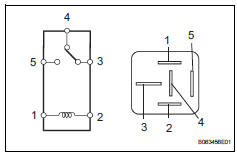
- Remove the heater relay from the instrument panel junction block.
- Measure the resistance of the relay.
Standard resistance 


- Inspect blower motor

- Disconnect the e54 motor connector.
- Connect the positive (+) lead from the battery to terminal 2 and the negative (-) lead to terminal 1, then check that the blower motor operates smoothly.
Ok: the blower motor operates smoothly.
- Measure the current.
Standard current 


- Check wire harness (heater control (blower switch) - battery)
- Disconnect the e24 heater control connector.
- Measure the voltage of the wire harness side connector.
Standard voltage 


- Inspect heater control (blower switch)

- Remove the heater control.
- Measure the resistance of the switch.
Standard resistance 


- Inspect blower resistor

- Remove the blower resistor.
- Measure the resistance of the resistor.
Standard resistance 


- Check wire harness (heater control (blower switch) - blower resistor)

- Disconnect the e24 heater control connector.
- Disconnect the e55 blower resistor connector.
- Measure the resistance of the wire harness side connectors.
Standard resistance 


- Check wire harness (blower resistor - blower motor)

- Disconnect the e55 blower resistor connector.
- Disconnect the e54 motor connector
- Measure the resistance of the wire harness side connectors.
Standard resistance 


- Check wire harness (blower motor - body ground)

- Disconnect the e54 motor connector.
- Measure the resistance of the wire harness side connector.
Standard resistance 
- Measure the voltage of the wire harness side connector.
Standard voltage 


- Check wire harness (air conditioning amplifier - battery)

- Disconnect the e36 amplifier connector.
- Measure the voltage of the wire harness side connector.
Standard voltage 


- Check wire harness (air conditioning amplifier - body ground)

- Disconnect the e36 amplifier connector.
- Measure the resistance of the wire harness side connector.
Standard resistance 


Proceed to next circuit inspection shown in problem symptoms table
 Multiplex communication circuit
Description
The air conditioning amplifier communicates data with the ecm and combination
meter through the can
communication system.
Wiring diagram
Inspection procedure
Check dt ...
 Compressor circuit
Description
When the a/c switch is turned on, the magnetic clutch on signal is sent from
the air conditioning
amplifier. Then the mg clt relay turns on to operate the magnetic clutch.
Wiring diag ...
Other materials:
Brake warning light remains on
Description
If any of the following conditions are detected, the brake warning light
remains on:
The ecu connectors are disconnected from the skid control ecu.
The brake fluid level is insufficient.
The parking brake is applied.
The ebd is defective.
Wiring diagram
Inspection p ...
Installation
Caution:
Be sure to read the precautionary notices concerning the
srs airbag system before servicing it (see page rs-1).
Install front passenger airbag assembly
Attach the rear side hook of the front passenger
airbag to the rear side airbag door.
Bend the front side hook so that it a ...
Engine compartment
Engine coolant reservoir
Engine oil filler cap
Battery
Brake fluid reservoir
Fuse box
Radiator
Condenser
Electric cooling fans
Engine oil level dipstick
Washer fluid tank
Engine oil
With the engine at operating temperature and turned off, check the oil
level on the dips ...
