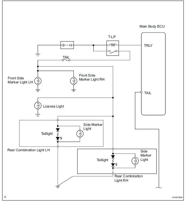
Toyota RAV4 (XA40) 2013-2018 Service Manual: Taillight relay circuit
Description
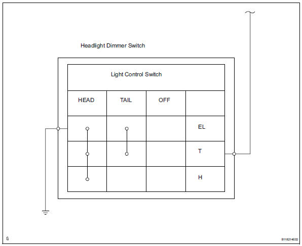
When the light control switch, located on the headlight dimmer switch, is turned to the tail position, the taillight relay (marking: t-lp) turns on to illuminate the front side marker lights, rear taillights, side marker lights and license plate light.
Wiring diagram
Inspection procedure
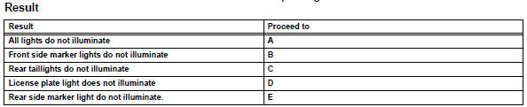
- Check whether lights illuminate
- Check whether the following lights illuminate: front side marker lights, rear taillights, side marker lights and license plate light.

- Inspect fuse (tail)
- Remove the tail fuse from the instrument panel junction block.
- Measure the resistance of the fuse.
Standard resistance:
below 1 

- Check wire harness (battery - instrument panel junction block)
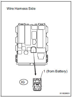
- Disconnect the ig instrument panel junction block connector.
- Measure the voltage of the wire harness side connector.
Standard voltage 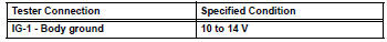

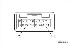
- Check wire harness (main body ecu - headlight dimmer switch)
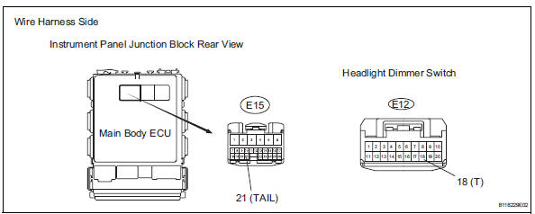
- Disconnect the e15 main body ecu connector.
- Disconnect the e12 headlight dimmer switch connector.
- Measure the resistance of the wire harness side connectors.
Standard resistance 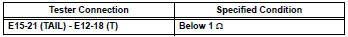

- Check wire harness (battery - headlight dimmer switch)
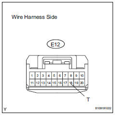
- Connect the e15 main body ecu connector.
- Disconnect the e12 headlight dimmer switch connector.
- Measure the voltage of the wire harness side connector.
Standard voltage 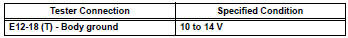

- Check wire harness (headlight dimmer switch - body ground)
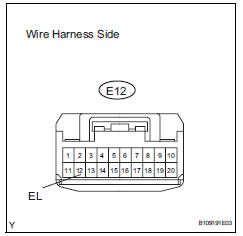
- Disconnect the e12 headlight dimmer switch connector.
- Measure the resistance of the wire harness side connector.
Standard resistance 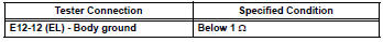

- Inspect headlight dimmer switch
- Remove the headlight dimmer switch.
- Measure the resistance of the switch.
Standard resistance 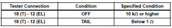

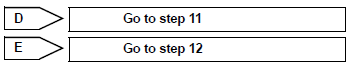
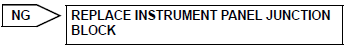
Replace instrument panel junction block
- Check instrument panel junction block (taillight relay)
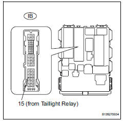
- Disconnect the ib instrument panel junction block connector.
- Measure the voltage of the junction block.
Standard voltage 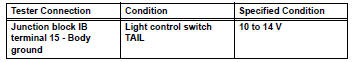

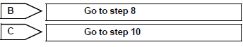
- Check wire harness (taillight relay - front side marker light and body ground)
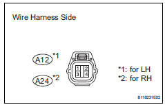
- Disconnect the a12 and a24 front side marker light connectors.
- Measure the voltage and resistance of the wire harness side connectors.
Standard resistance 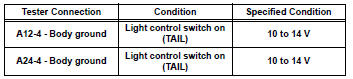
standard resistance 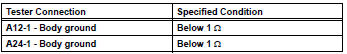

Replace bulb
- Check wire harness (main body ecu - rear combination light)
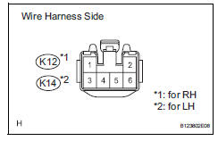
- Disconnect the k12 and k14 rear combination light connectors.
- Measure the voltage and resistance of the wire harness side connectors.
Standard voltage 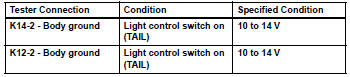
Standard resistance 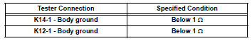

Replace rear combination light
- Check wire harness (main body ecu - license plate light and body ground)
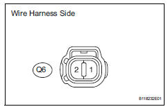
- Disconnect the q6 license plate light connector.
- Measure the voltage and resistance of the wire harness side connector.
Standard voltage 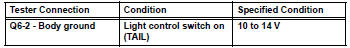
Standard resistance 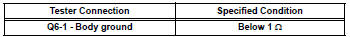

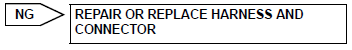
Replace bulb
- Check wire harness (main body ecu - rear combination light)
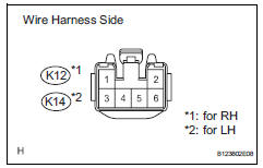
- Disconnect the k12 and k14 rear combination light connectors.
- Measure the voltage and resistance of the wire harness side connectors.
Standard voltage 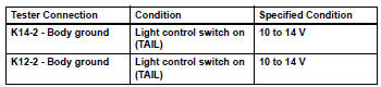
Standard resistance 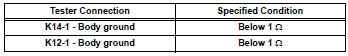

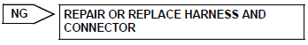
Replace bulb
 Illumination circuit
Description
The main body ecu receives information regarding the door courtesy switch and
door lock position
switch, and turns on the room light.
Wiring diagram
Inspection procedure
Perf ...
 Headlight assembly
Components
Removal
Hint:
Use the same procedures for the rh and lh sides.
The procedures listed below are for the lh side.
Disconnect cable from negative battery
terminal
Rem ...
Other materials:
Bluetooth® phone
settings
You can adjust the hands-free system to your desired settings.
“Phone/message settings” screen
To display the screen shown below, press the “setup” button, and
select “phone” on the “setup” screen.
Set the phone connection
Setting the sound
Contact/call history settings
...
Seat position airbag sensor circuit malfunction
Description
The seat position sensor circuit consists of the center airbag sensor and the
seat position sensor.
Dtc b1653/35 is recorded when a malfunction is detected in the seat position
sensor circuit.
Wiring diagram
Inspection procedure
Check for dtc
Turn the ...
Brake switch "B" circuit high
Description
The purpose of this circuit is to prevent the engine from stalling while
driving in the lock-up condition when
the brakes are suddenly applied.
When the brake pedal is depressed, this switch sends a signal to the ecm. Then
the ecm cancels the
operation of the lock-up clutch ...
