Toyota RAV4 (XA40) 2013-2018 Service Manual: Disassembly (2006/01- )
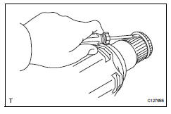
- Remove front axle inboard joint boot no. 2 Clamp
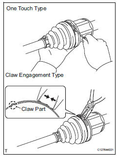
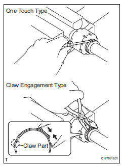
- One touch type: using a screwdriver, remove the inboard joint boot clamp, as shown in the illustration.
- Claw engagement type: using needle-nose pliers, remove the inboard joint boot clamp, as shown in the illustration.
- Remove front axle inboard joint boot clamp
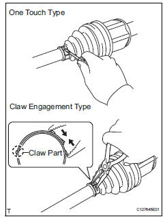
- One touch type: using a screwdriver, remove the inboard joint boot clamp, as shown in the illustration.
- Claw engagement type: using needle-nose pliers, remove the inboard joint boot clamp, as shown in the illustration.
- Remove front axle inboard joint boot
- Remove the boot from the inboard joint.
- Remove front drive inboard joint assembly lh
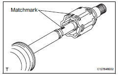
- Remove any old grease from the inboard joint.
- Put matchmarks on the inboard joint and outboard joint shaft.
Notice:
Do not punch the marks.
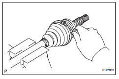
- Remove the inboard joint from the outboard joint shaft.
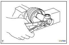
- Using a snap ring expander, remove the shaft snap ring.
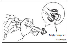
- Put matchmarks on the outboard joint shaft and tripod joint.
Notice:
Do not punch the marks.
- Using a brass bar and hammer, tap out the tripod joint from the outboard joint shaft.
Notice:
Do not tap the rollers.
- Remove the inboard joint boot.
- Remove front drive inboard joint assembly rh
Hint:
Use the same procedures described for the lh side.
- Remove front drive shaft damper clamp lh
- One touch type: using a screwdriver, remove the drive shaft damper clamp, as shown in the illustration.
- Claw engagement type: using needle-nose pliers, remove the drive shaft damper clamp, as shown in the illustration.
- Remove front drive shaft damper lh
- Remove the front drive shaft damper from the outboard joint shaft.
- Remove front axle outboard joint boot no. 2 Clamp
- Using a screwdriver, remove the outboard joint boot clamp, as shown in the illustration.
- Remove front axle outboard joint boot clamp
- Using a screwdriver, remove the outboard joint boot clamp, as shown in the illustration.
- Remove front axle outboard joint boot
- Remove the outboard joint boot from the outboard joint shaft.
- Remove any old grease from the outboard joint.
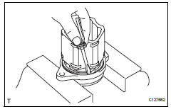
- Remove front drive shaft hole snap ring lh
- Using a screwdriver, remove the hole snap ring.
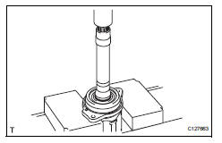
- Remove front drive shaft dust cover lh
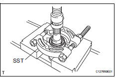
- Using sst and a press, press out the shaft dust cover.
Sst 09950-00020
Notice:
Be careful not to drop the inboard joint.
- Remove front drive shaft dust cover rh
Hint:
Use the same procedures described for the lh side.
- Remove drive shaft bearing case (for rh)
- Using a screwdriver, remove the bearing case snap ring.
- Using a press, press out the drive shaft bearing case.
Hint:
Be careful not to drop the inboard joint.
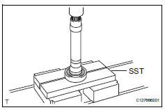
- Remove front drive shaft dust cover (for rh)
- Using sst and a press, press out the drive shaft dust cover.
Sst 09950-00020
Notice:
Be careful not to drop the inboard joint.
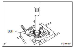
- Remove front drive shaft bearing
- Using a snap ring expander, remove the snap ring.
- Using sst and a press, press out the drive shaft bearing.
Sst 09527-10011
- Remove the bearing case snap ring.
 Disassembly (2005/11-2006/01)
Remove front axle inboard joint boot no. 2 Clamp lh
One touch type:
Using a screwdriver, remove the inboard joint
boot clamp, as shown in the illustration.
Claw engagement t ...
 Reassembly (2005/11-2006/01)
Install drive shaft bearing case subassembly
Using sst and a press, press in the drive shaft
bearing case to the inboard joint rh.
Sst 09527-10011, 09710-04081
Notice:
The bearing ...
Other materials:
Rear speed sensor (for 4wd)
Components
Removal
Hint:
Use the same procedures for the lh side and rh side.
The procedures listed below are for the lh side.
Disconnect cable from negative battery
terminal
Caution:
Wait at least 90 seconds after disconnecting the
cable from the negative (-) battery termin ...
Customize parameters
Hint:
The following items can be customized.
Notice:
When the customer requests a change in a function,
first make sure that the function can be customized.
Be sure to make a note of the current settings before
customizing.
When troubleshooting a function, first make sure that
the fu ...
Washer motor
Components
Removal
Disconnect cable from negative battery
terminal
Caution:
Wait at least 90 seconds after disconnecting the
cable from the negative (-) battery terminal to
prevent airbag and seat belt pretensioner activation.
Remove washer inlet sub-assembly
Remove th ...
