Toyota RAV4 (XA40) 2013-2018 Service Manual: Reassembly (2005/11-2006/01)
- Install drive shaft bearing case subassembly

- Using sst and a press, press in the drive shaft bearing case to the inboard joint rh.
Sst 09527-10011, 09710-04081
Notice:
The bearing should be installed completely.

- Using a snap ring expander, install a new drive shaft hole snap ring.
- Install front drive shaft dust cover

- Using sst and a press, press in a new drive shaft dust cover.
Sst 09726-40010, 09527-10011
Notice:
Be careful not to damage the dust cover.
- Install front drive shaft dust cover rh
- Using sst and a press, press in a new drive shaft dust cover until the distance from the tip of the center drive shaft to the drive shaft dust cover reaches the specification, as shown in the illustration.

Sst 09527-10011
Standard distance: 91.0 To 92.0 Mm (3.583 To 3.622 In.)
Notice:
- The dust cover should be installed completely.
- Be careful not to damage the dust cover.
- Install front drive shaft dust cover lh

- Using sst and a press, press in a new drive shaft dust cover.
Sst 09527-10011
Notice:
- The dust cover should be installed completely.
- Be careful not to damage the dust cover.
- Install front drive shaft lh hole snap ring
- Install a new hole snap ring.
- Install front axle outboard joint boot

Hint:
Before installing the boots, wrap the spline of the drive shaft with vinyl tape to prevent the boots from being damaged.
- Install new parts to the outboard joint shaft in the following order.
- No. 2 Outboard joint boot clamp
- Outboard joint boot
- Outboard joint boot clamp
- Pack the outboard joint shaft and boot with grease from the boot kit.
Standard grease capacity: 190 to 200 g (6.7 To 7.1 Oz.)
- Install front axle outboard joint boot no. 2 Clamp lh
Caution:
Wear protective gloves while performing the operation and be careful to avoid cutting your hands or other body parts.

- Install a new boot clamp to the outboard joint boot and temporarily bend the lever.
Notice:
- When temporarily bending the lever, make sure not to deform the band and lever.
- Set the clamp correctly in the guide groove and align it with the interior of the vehicle as much as possible.

- With the joint on the working surface, use your body
weight to press down on the joint with one hand.
Then, roll the joint forward, as shown in the illustration, and press the lever in until a "click" sound is heard.
Notice:
- Do not damage the deflector.
- Make sure the joint is in full contact with the joint surface at all times.

- Using a plastic-faced hammer, fix the buckle into place by tapping it. At the same time, use the plastic-faced hammer to adjust the lift of the lever so that the gaps between the buckle flange and lever end flange become even.
Notice:
Do not damage the boot.
- Install front axle outboard joint boot no. 2 Clamp rh
Hint:
Use the same procedures described for the lh side.
- Install front axle outboard joint boot clamp lh

Caution:
Wear protective gloves while performing the operation and be careful to avoid cutting your hands or other body parts.
- Install a new boot clamp to the outboard joint boot and temporarily bend the lever.
Notice:
When temporarily bending the lever, make sure not to deform the band and lever.

- Using water pump pliers, temporarily lock the boot clamp by clamping it down until a "click" sound is heard.

- Using a plastic-faced hammer, fix the buckle into place by tapping it. At the same time, use the plastic-faced hammer to adjust the lift of the lever so that the gaps between the buckle flange and lever end flange become even.
Notice:
Do not strike the drive shaft forcefully with the plastic-faced hammer.
- Install front axle outboard joint boot rh clamp
Hint:
Use the same procedures described for the lh side.
- Install front drive shaft damper lh

Hint:
Install the damper clamp to outboard joint side.
- Install a new drive shaft damper clamp and the drive shaft damper to the drive shaft.
- Make sure that the damper is on the shaft groove.
- Set the distance, as described below.
Standard distance: 161 to 165 mm (6.339 To 6.496 In.)
- Install front drive shaft damper clamp lh
- Hold the front drive shaft lightly in a soft vise.
- Install the drive shaft damper clamp to the damper.
Notice:
Be sure to install the clamp in the correct position.
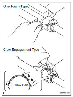
- One touch type:
- Using a screwdriver, install the drive shaft damper clamp, as shown in the illustration.
- Claw engagement type:
- Using needle-nose pliers, install the drive shaft damper clamp, as shown in the illustration.
- Install front drive inboard joint assembly lh

- Wrap the spline of the outboard joint shaft with vinyl tape to prevent the boots from being damaged.
- Install new parts to the outboard joint shaft in the following order.
- Inboard joint boot clamp
- No. 2 Inboard joint boot clamp
- Inboard joint boot
- Place the beveled side of the tripod axial spline toward the outboard joint.
- Align the matchmarks placed before removal.
- Using a brass bar and hammer, tap the tripod joint onto the drive shaft.
Notice:
- Do not tap the rollers.
- Be sure to install the tripod joint in the correct direction.
- Pack the inboard joint shaft and boot with grease from the boot kit.
Standard grease capacity: 175 to 185 g (6.2 To 6.5 Oz.)

- Using a snap ring expander, install a new shaft snap ring.
- Align the matchmarks, and install the inboard joint to the outboard joint shaft.
- Install front drive inboard joint assembly rh
Hint:
Use the same procedures described for the lh side.
- Install front axle inboard joint boot
- Install the inboard joint boot to the inboard joint.
- Install front axle inboard joint boot clamp lh

- One touch type:
- Using a screwdriver, install the inboard joint boot clamp, as shown in the illustration.
Notice:
Be careful not to damage the boot.
- Claw engagement type:
- Using needle-nose pliers, install the inboard joint boot clamp, as shown in the illustration.
Notice:
Be careful not to damage the boot.
- Install front axle inboard joint boot clamp rh
Hint:
Use the same procedures described for the lh side.
- Install front axle inboard joint boot no. 2 Clamp lh

- One touch type:
- Using a screwdriver, install the no. 2 Inboard joint boot clamp, as shown in the illustration.
Notice:
Be careful not to damage the boot.
- Claw engagement type:
- Using needle-nose pliers, install the no. 2 Inboard joint boot clamp, as shown in the illustration.
Notice:
Be careful not to damage the boot.
- Install front axle inboard joint boot no. 2 Clamp rh
Hint:
Use the same procedures described for the lh side.
- Inspect front drive shaft

- Check that there is no severe play in the radial direction of the outboard joint.
- Check that the inboard joint slides smoothly in the thrust direction.
- Check that there is no severe play in the radial direction of the inboard joint.

- Check the boots for damage.
Notice:
Keep the drive shaft assembly level during inspection.
Hint:
For dimension (a), refer to the following values.
Reference value:
585.2 Mm (23.039 In.) For lh side
902 Mm (35.512 In.) For rh side
 Disassembly (2006/01- )
Remove front axle inboard joint boot no. 2 Clamp
One touch type:
using a screwdriver, remove the inboard joint boot
clamp, as shown in the illustration.
Claw engagement type:
usin ...
 Reassembly (2006/01- )
Install drive shaft bearing case subassembly
(for rh)
Install the bearing snap ring.
Using sst and a press, press in the drive shaft
bearing case to the inboard joint rh.
Sst 095 ...
Other materials:
Front passenger side seat belt warning light malfunction
Description
When the ignition switch is on, the center airbag sensor transmits front seat
inner belt status signals to
the combination meter through the can bus line. If the front passenger seat belt
is not fastened, the
heater control panel (automatic a/c) or clock (manual a/c) blinks the fr ...
Fuel pump control circuit
Description
When the engine is cranked, the starter relay drive signal output from the
star terminal of the ecm is
input into the sta terminal of the ecm, and ne signal generated by the
crankshaft position sensor is also
input into the ne+ terminal. Thus, the ecm interprets that the engine is ...
Using the steering
wheel switches
The steering wheel switches can be used to operate a connected
cellular phone.
Operating a telephone using the steering wheel switches
Volume switch
Increase/decrease the volume
Press and hold:
continuously increase/
decrease the volume
Enter switch
Select an item
...
