Toyota RAV4 (XA40) 2013-2018 Service Manual: Disassembly (2005/11-2006/01)
- Remove front axle inboard joint boot no. 2 Clamp lh
- One touch type:
- Using a screwdriver, remove the inboard joint boot clamp, as shown in the illustration.

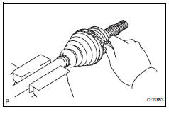
- Claw engagement type:
- Using needle-nose pliers, remove the inboard joint boot clamp, as shown in the illustration.
- Remove front axle inboard joint boot no. 2 Clamp rh
Hint:
Use the same procedures described for the lh side.
- Remove front axle inboard joint boot clamp lh

- One touch type:
- Using a screwdriver, remove the inboard joint boot clamp, as shown in the illustration.
- Claw engagement type:
Using needle-nose pliers, remove the inboard joint boot clamp, as shown in the illustration.
- Remove front axle inboard joint boot clamp rh
Hint:
Use the same procedures described for the lh side.
- Remove front axle inboard joint boot
- Remove the boot from the inboard joint.
- Remove front drive inboard joint assembly lh

- Remove any old grease from the inboard joint.
- Put matchmarks on the inboard joint and outboard joint shaft.
Notice:
Do not punch the marks.
- Remove the inboard joint from the outboard joint shaft.
- Using a snap ring expander, remove the shaft snap ring.


- Put matchmarks on the outboard joint shaft and tripod joint.
Notice:
Do not punch the marks.
- Using a brass bar and hammer, tap out the tripod joint from the outboard joint shaft.
Notice:
Do not tap the rollers.
- Remove the inboard joint boot.
- Remove front drive shaft damper clamp lh

- One touch type:
- Using a screwdriver, remove the drive shaft damper clamp, as shown in the illustration.
- Claw engagement type:
Using needle-nose pliers, remove the drive shaft damper clamp, as shown in the illustration.
- Remove front drive shaft damper lh
- Remove the front drive shaft damper from the outboard joint shaft.
- Remove front axle outboard joint boot no. 2 Clamp lh
- Using a screwdriver, remove the outboard joint boot clamp, as shown in the illustration.
- Remove front axle outboard joint boot clamp lh
- Using a screwdriver, remove the outboard joint boot clamp, as shown in the illustration.

- Remove front axle outboard joint boot
- Remove the outboard joint boot from the outboard joint shaft.
- Remove any old grease from the outboard joint.
- Remove front drive shaft hole snap ring lh

- Using a screwdriver, remove the hole snap ring.
- Remove front drive shaft dust cover lh

- Using sst and a press, press out the shaft dust cover
Sst 09950-00020
Notice:
Be careful not to drop the inboard joint
- Remove front drive shaft dust cover rh
Hint:
Use the same procedures described for the lh side.
- Remove drive shaft bearing case

- Using a screwdriver, remove the bearing case snap ring.

- Using a press, press out the drive shaft bearing case.
Hint:
Be careful not to drop the inboard joint
- Remove front drive shaft dust cover

- Using sst and a press, press out the drive shaft dust cover.
Sst 09950-00020
Hint:
Be careful not to drop the inboard joint
- Remove front drive shaft bearing

- Using a snap ring expander, remove the snap ring.

- Using sst and a press, press out the drive shaft bearing.
Sst 09527-10011
- Remove the snap ring.
 Removal
(2006/01- )
Removal
(2006/01- )
Remove front wheel
Drain automatic transaxle fluid
Drain the automatic transaxle fluid for u140f (see
page ax-147).
Drain the automatic transaxle fluid for u241e (see
page ax-146).
...
 Disassembly (2006/01- )
Remove front axle inboard joint boot no. 2 Clamp
One touch type:
using a screwdriver, remove the inboard joint boot
clamp, as shown in the illustration.
Claw engagement type:
usin ...
Other materials:
Back-up light circuit
Description
The park / neutral position switch turns on when the shift lever is moved
into the r position, causing the
back-up lights to illuminate.
Wiring diagram
Inspection procedure
Inspect fuse (gauge1)
Remove the gauge1 fuse from the instrument panel
junction block.
Meas ...
Slip indicator light does not come on
Description
Refer to the description of "slip indicator light remains on" (see page
bc-152).
Wiring diagram
Refer to the slip indicator light circuit (see page bc-152).
Inspection procedure
Notice:
When replacing the abs and traction actuator, perform the zero point
calibration ( ...
Dtc check / clear
Check dtc
When using intelligent tester:
Connect the intelligent tester (with can vim) to
the dlc3.
Turn the ignition switch on and press the
intelligent tester main switch on.
Read the dtcs by following the prompts on the
intelligent tester.
Hint:
Refer to the intel ...
