Toyota RAV4 (XA40) 2013-2018 Service Manual: Compressor solenoid circuit (2005/11-2006/01)

Description
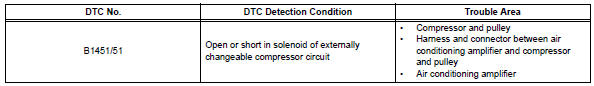
In this circuit, the compressor receives a refrigerant compression demand signal from the air conditioning amplifier. Based on this signal, the compressor changes the degree of refrigerant compression.
Wiring diagram

Inspection procedure
- Read value of intelligent tester (reg ctrl currnt)
- Connect the intelligent tester (with can vim) to the dlc3.
- Turn the ignition switch on and turn the intelligent tester main switch on.
- Select the items below in the data list, and read the value displayed on the intelligent tester.
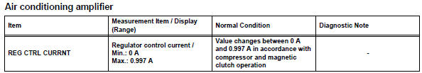
Ok: the display is as specified in the normal condition column.


- Inspect compressor and pulley

- Disconnect the compressor and pulley connector.
- Measure the resistance of the connector.
Standard resistance 


- Check wire harness (compressor and pulley - air conditioning amplifier)

- Disconnect the b23 compressor and pulley connector.
- Disconnect the e36 amplifier connector.
- Measure the resistance of the wire harness side connectors.
Standard resistance 


- Check wire harness (compressor and pulley - body ground)
- Disconnect the b23 compressor and pulley connector.
- Measure the resistance of the wire harness side connector.
Standard resistance


Replace air conditioning amplifier
 Pressure sensor circuit
Description
This dtc is output when the refrigerant pressure is either extremely low
(0.19 Mpa [2.0 Kgf/cm2, 28 psi]
or less) or extremely high (3.14 Mpa [32.0 Kgf/cm2, 455 psi] or more). The ...
 Compressor solenoid circuit (2006/01- )
Description
In this circuit, the compressor receives a refrigerant compression demand
signal from the air conditioning
amplifier. Based on this signal, the compressor changes the degree of
ref ...
Other materials:
Operating instructions
Turning the end of the lever turns on the lights as follows:
Type a
The side marker, parking,
tail, license plate, daytime
running lights and instrument
panel lights turn on.
The headlights and all
lights listed above (except
daytime running lights)
turn on.
The headlights an ...
System check
Hint:
Performing a system check enables the system,
which consists of multiple actuators, to be operated
without removing any parts. In addition, it can show
whether or not any dtcs are set, and can detect
potential malfunctions in the system. The system
check can be performed with the intelli ...
For vehicles equipped with mobile communication systems
Install the antenna as far away from the ecu and
sensors of the vehicle electronic systems as
possible.
Install an antenna feeder at least 20 cm (7.87 In.)
Away from the ecu and sensors of the vehicle
electronic systems. For details about ecu and
sensor locations, refer to the sec ...
