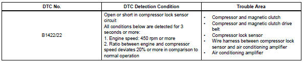
Toyota RAV4 (XA40) 2013-2018 Service Manual: Compressor lock sensor circuit
![]()
Description
This sensor sends 1 pulse per engine revolution to the air conditioning amplifier. If the ratio of the compressor speed divided by the engine speed is smaller than a predetermined value, the air conditioning amplifier turns the compressor off, and the indicator blinks at approximately 1 second intervals.
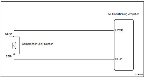
Wiring diagram
Inspection procedure
- Check air conditioning amplifier (lock signal)
- Remove the air conditioning amplifier with its connectors still connected.
- Check the waveform of the amplifier connector.
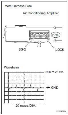
Ok:
waveform is as shown in the illustration.


- Inspect compressor lock sensor
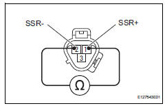
- Disconnect the b47 compressor lock sensor connector.
- Measure the resistance of the sensor.
Standard resistance 


- Check wire harness (compressor lock sensor - air conditioning amplifier)
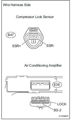
- Disconnect the b47 compressor lock sensor connector.
- Disconnect the e36 amplifier connector.
- Measure the resistance of the wire harness side connectors.
Standard resistance 


Replace air conditioning amplifier
 Evaporator temperature sensor circuit
Description
The no. 1 Cooler thermistor (evaporator temperature sensor) is installed on
the evaporator in the air
conditioning unit to detect the temperature of the cooled air that has passed ...
 Pressure sensor circuit
Description
This dtc is output when the refrigerant pressure is either extremely low
(0.19 Mpa [2.0 Kgf/cm2, 28 psi]
or less) or extremely high (3.14 Mpa [32.0 Kgf/cm2, 455 psi] or more). The ...
Other materials:
Basic inspection
When measuring resistance of
electronic parts
Unless otherwise stated, all resistance
measurements should be made at an ambient
temperature of 20°c (68°f). Resistance
measurements may be inaccurate if measured
at high temperatures, i.E. Immediately after the
vehicle has been r ...
Random / multiple cylinder misfire detected
Description
When the engine misfires, high concentrations of hydrocarbons (hc) enter the
exhaust gas. Extremely
high hc concentration levels can cause increases in exhaust emission levels.
High concentrations of hc
can also cause increases in the three-way catalytic converter (twc) te ...
Fuel pressure regulator
Components
Removal
Remove fuel tank assembly
Remove the fuel tank (see page fu-39).
Remove fuel tank main tube sub-assembly
Remove the joint clip and fuel tank main tube.
Caution:
Before removing the tube joint clip, check for
foreign matter around the cli ...
