Toyota RAV4 (XA40) 2013-2018 Service Manual: Ambient temperature sensor circuit
![]()
Description
The ambient temperature sensor is installed in the front part of the condenser to detect the ambient temperature and control the air conditioner. The sensor is connected to the combination meter and detects fluctuations in the ambient temperature. This data is used for controlling the room temperature.
The sensor sends a signal to the air conditioning amplifier via the combination meter. The resistance of the ambient temperature sensor changes in accordance with the ambient temperature. As the temperature decreases, the resistance increases. As the temperature increases, the resistance decreases.
The air conditioning amplifier applies a voltage (5 v) to the ambient temperature sensor and reads voltage changes as changes in the resistance of the ambient temperature sensor. The combination meter sends the read signal to the air conditioning amplifier via can communication.

Wiring diagram

Inspection procedure
- Read value of intelligent tester (ambi temp sens)
- Connect the intelligent tester (with can vim) to the dlc3.
- Turn the ignition switch on and turn the intelligent tester main switch on.
- Select the item below in the data list, and read the value displayed on the intelligent tester.
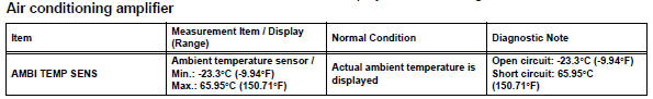
Ok: the display is as specified in the normal condition column.


- Inspect ambient temperature sensor

- Remove the ambient temperature sensor.
- Measure the resistance of the sensor.
Standard resistance 
Notice:
- Touching the sensor even slightly may change the resistance value. Be sure to hold the connector of the sensor.
- When measuring, the sensor temperature must be the same as the ambient temperature.
Hint:
As the temperature increases, the resistance decreases (see the graph).


- Check wire harness (ambient temperature sensor - combination meter)

- Disconnect the a17 sensor connector.
- Disconnect the e19 meter connector.
- Measure the resistance of the wire harness side connectors.
Standard resistance 


Replace combination meter
 Diagnostic trouble code chart (2006/01- )
Hint:
When the air conditioning system functions properly, dtc
b1400/00 is output.
Hint:
*1: Dtc b1422/22 (compressor lock sensor circuit) is
indicated only for a currently occurring malfunct ...
 Evaporator temperature sensor circuit
Description
The no. 1 Cooler thermistor (evaporator temperature sensor) is installed on
the evaporator in the air
conditioning unit to detect the temperature of the cooled air that has passed ...
Other materials:
Vehicle load limits
Vehicle load limits include total load capacity, seating capacity,
twr (trailer weight rating) and cargo capacity.
Total load capacity (vehicle capacity weight)
Total load capacity means the combined weight of occupants, cargo
and luggage.
Seating capacity: 5 occupants (front 2, rear 3)
Seatin ...
Rear window wiper
and washer
Turning the end of the lever turns on the rear window wiper, and pushing
the lever away from you turns on the rear window wiper and
washer.
For the u.S.A.
Intermittent operation
Normal operation
Washer/wiper dual operation
For Canada
Intermittent operation
Normal oper ...
Driving mode select switch
The driving modes can be
selected to suit the driving
and usage conditions.
Selecting a driving mode
â– FF vehicles/Dynamic
Torque Control AWD vehicles
Eco drive mode
Suitable for driving to improve fuel
economy by more smoothly generating
torque in response to accelerator
pedal operations comp ...
