Toyota RAV4 (XA40) 2013-2018 Service Manual: Air conditioning control panel does not operate
Description
This circuit consists of the air conditioning control and the air conditioning amplifier. When the air conditioning control is operated, signals are transmitted to the air conditioning amplifier through the lin communication system.
If the lin communication system malfunctions, the air conditioning amplifier does not operate even if the air conditioning control is operated.
Wiring diagram

Inspection procedure
- Check wire harness (air conditioning control assembly - body ground)

- Disconnect the air conditioning control assembly connector.
- measure the resistance of the wire harness side connector.
Standard resistance


- Check wire harness (air conditioning control assembly - battery)

- Disconnect the e23 air conditioning control assembly connector.
- Measure the voltage of the wire harness side connector.
Standard voltage


- Check wire harness (air conditioning amplifier - air conditioning control)
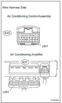
- Disconnect the e23 control connector.
- Disconnect the e37 amplifier connector.
- Measure the resistance of the wire harness side connectors.
Standard resistance


- Replace air conditioning amplifier
- Replace the air conditioning control with a new or properly functioning one.
- Operate the air conditioning control to check that it functions properly.


Replace air conditioning amplifier
 Multiplex communication circuit
Description
The air conditioning amplifier communicates data with the ecm and combination
meter through the can
communication system.
Wiring diagram
Inspection procedure
Check dt ...
 Blower motor circuit
Description
The blower motor is operated by signals from the air conditioning amplifier.
Blower motor speed signals
are transmitted in accordance with changes in the duty ratio.
Wiring diagra ...
Other materials:
Headlight relay
On-vehicle inspection
Remove headlight relay
Remove the headlight relay from the engine room
no. 2 Relay block.
Measure the resistance of the relay.
Standard resistance
If result is not as specified, replace the relay. ...
Trailer Tongue Weight
A recommended tongue
weight varies in accordance
with the types of trailers or
towing as described below.
To ensure the recommended
values shown below, the
trailer must be loaded by
referring to the following
instructions.
Tongue Weight
The gross trailer weight should be
distribut ...
Inspection
Inspect crankshaft position sensor
Measure the resistance of the sensor.
Standard resistance
Notice:
Cold and hot mean the temperature of the coils
themselves. Cold is from -10 to 50°c (14 to
122°f) and hot is from 50 to 100°c (122 to
212°f).
If the result is not as specif ...
