Toyota RAV4 (XA40) 2013-2018 Service Manual: Vc output circuit
Description
The ecm constantly generates 5 v power from the battery voltages supplied to the +b (batt) terminal to operate the microprocessor. The ecm also provides this power to the sensors through the vc output circuit.

When the vc circuit is short-circuited, the microprocessor in the ecm and sensors that are supplied with power through the vc circuit are inactivated because the power is not supplied from the vc circuit. Under this condition, the system does not start up and the mil does not illuminate even if the system malfunctions.
Hint:
Under normal conditions, the mil is illuminated for several seconds when the ignition switch is first turned on. The mil goes off when the engine is started.
Wiring diagram

Inspection procedure
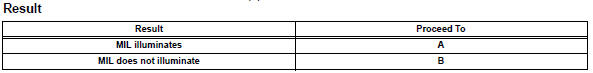
- Check mil
- Check that the malfunction indicator lamp (mil) lights up when turning the ignition switch on.
Ok: mil lights up


- Check communication between intelligent tester and ecm
- Connect the intelligent tester to the dlc3.
- Turn the ignition switch on and tester on.
- Check the communication between the tester and ecm.


- Check mil (throttle position sensor)
- Disconnect the b3 throttle body connector.
- Turn the ignition switch on.
- Check the mil.
- Reconnect the throttle body connector.


- Check mil (accelerator pedal position sensor)
- Disconnect the a4 accelerator pedal position sensor connector.
- Turn the ignition switch on.
- Check the mil.

- Reconnect the accelerator pedal position sensor connector.


- Check mil (canister pump module)

- Disconnect the s3 canister pump module connector.
- Turn the ignition switch on.
- Check the mil.

- Reconnect the canister pump module connector.


- Check mil (battery current sensor)
- Disconnect the b29 battery current sensor connector.
- Turn the ignition switch on.
- Check the mil.

- Reconnect the battery current sensor connector.


- Check harness and connector
- Disconnect the b3 throttle body connector.
- Disconnect the a4 accelerator pedal position sensor connector.
- Disconnect the s3 canister pump module connector.
- Disconnect the b29 battery current sensor connector.
- Disconnect the a9 and b30 ecm connectors.
- Measure the resistance.
Standard resistance (check for short)

- Reconnect the throttle body connector.
- Reconnect the accelerator pedal position sensor connector.
- Reconnect the canister pump module connector.
- Reconnect the battery current sensor connector.
- Reconnect the ecm connectors.


 Ecm power source circuit
Description
When the ignition switch is turned on, the battery voltage is applied to the
igsw of the ecm. The output
signal from the mrel terminal of the ecm causes a current to flow to the coil, ...
 Fuel pump control circuit
Description
When the engine is cranked, the starter relay drive signal output from the
star terminal of the ecm is
input into the sta terminal of the ecm, and ne signal generated by the
cranksha ...
Other materials:
Fog light relay
On-vehicle inspection
Inspect front fog light relay
Remove the front fog relay from the no. 6 Relay
block.
Measure the resistance of the relay.
Standard resistance
If the result is not as specified, replace the relay. ...
Front occupant classification sensor lh circuit
malfunction
Description
The front occupant classification sensor lh circuit consists of the occupant
classification ecu and the
front occupant classification sensor lh.
Dtc b1780 is recorded when a malfunction is detected in the front occupant
classification sensor lh
circuit.
Wiring diagram
...
Tire pressure warning ecu
Components
Removal
Disconnect cable from negative battery
terminal
Caution:
Wait at least 90 seconds after disconnecting the
cable from the negative (-) battery terminal to
prevent airbag and seat belt pretensioner activation.
Remove glove compartment door
assembly (see page i ...
