Toyota RAV4 (XA40) 2013-2018 Service Manual: Fuel pump control circuit
Description
When the engine is cranked, the starter relay drive signal output from the star terminal of the ecm is input into the sta terminal of the ecm, and ne signal generated by the crankshaft position sensor is also input into the ne+ terminal. Thus, the ecm interprets that the engine is cranked, and turns the transistor tr1 in the ecm internal circuit on. The current flows to the c/opn (circuit opening) relay by turning the tr1 on. Then, the fuel pump operates.
While the ne signal is input into the ecm, when the engine is running, the ecm turns the tr1 on continuously.
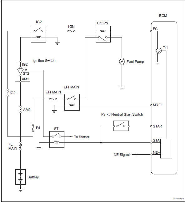
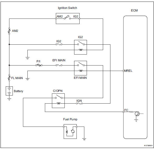
Wiring diagram
Inspection procedure
- Perform active test using intelligent tester (fuel pump/spd)
- Connect the intelligent tester to the dlc3.
- Turn the ignition switch on and turn the tester on.
- Select the following menu items: diagnosis / enhanced obd ii / active test / fuel pump / spd.
- Check whether the fuel pump operating sound occurs when performing the active test on the tester.
Ok: fuel pump operating sound occurs.

- Inspect instrument panel junction block assembly (c/opn relay input voltage)
- Measure the voltage between the terminal of the instrument panel junction block (j/b) and the body ground when the ignition switch is turned on and off.
Standard voltage 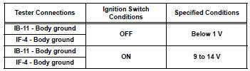
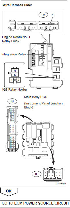
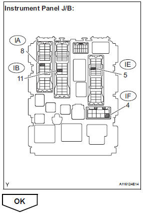
- Check harness and connector (instrument panel j/b - integration relay, ig2 relay)
- Remove the integration relay and ig2 relay from the engine room no. 1 Relay block.
- Disconnect the instrument panel junction block connector.
- Check the resistance.
Standard resistance (check for open)
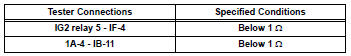
Standard resistance (check for short)
- Reinstall the integration relay and ig2 relay.
- Reconnect the instrument panel junction block connector.
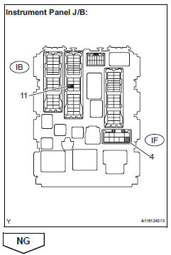
- Inspect instrument panel junc.ssembly (c/opn relay)
- Remove the instrument panel junction block.
- Measure the c/opn relay resistance.
Standard resistance 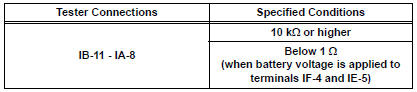
Hint:
Relay coil circuit between if-4 and ie-5 is not through ign fuse.
- Reinstall the instrument panel junction block.
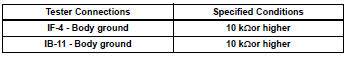
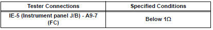
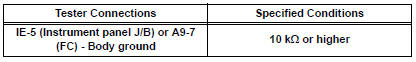
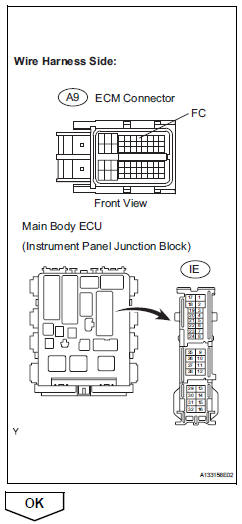
- Check harness and connector (instrument panel j/b - ecm)
- Disconnect the a9 ecm connector.
- Disconnect the ie connector from instrument panel junction block.
- Measure the resistance.
Standard resistance (check for open)
Standard resistance (check for short)
- Reconnect the instrument panel junction block and the ecm connectors.
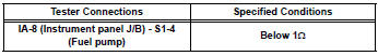
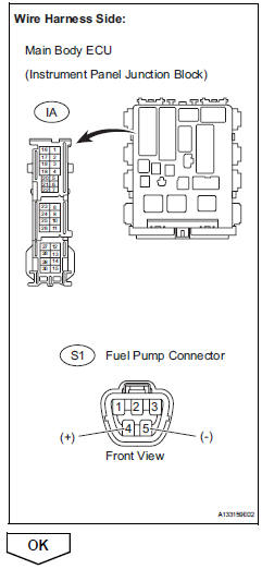
- Check harness and connector (c/opn relay - fuel pump - body ground)
- Check the harness and the connectors between the instrument panel junction block assembly and the fuel pump.
- Disconnect the ia instrument panel junction block connector.
- Disconnect the s1 fuel pump connector.
- Measure the resistance.
Standard resistance (check for open)
Standard resistance (check for short)
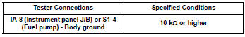
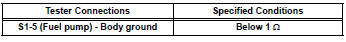
- Check the harness and the connectors between the fuel pump and the body ground.
- Disconnect the s1 fuel pump connector.
- Measure the resistance.
Standard resistance (check for open)
- Reconnect the instrument panel junction block connector
- Reconnect the fuel pump connector.
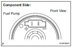
- Inspect fuel pump
- Inspect fuel pump resistance.
- Measure the resistance between the terminals.
Standard resistance: 0.2 To 3.0 ٠at 20°c(68°f)
- Inspect fuel pump operation.
- Apply the battery voltage to both the terminals.
Notice:
- These tests must be done quickly (within 10 seconds) to prevent the coil from burning out.
- Keep the fuel pump as far away from the battery as possible.
- Always turn the voltage on and off on the battery side, not the fuel pump side.
- Read value using intelligent tester (starter sig)
- Connect the intelligent tester to the dlc3.
- Turn the ignition switch on and turn the tester on.
- Select the following menu items: diagnosis / enhanced obd ii / data list / primary / starter sig.
- Check the result when the ignition switch is turned to on and start.
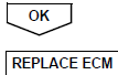
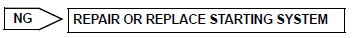
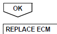
Ok 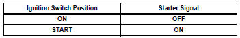

- Read value using intelligent tester (engine spd)
- Connect the intelligent tester to the dlc3.
- Turn the ignition switch on and turn the tester on.
- Select the following menu items: diagnosis / enhanced obd ii / data list / primary / engine spd.
- Read the values displayed on the tester while cranking.
Standard: values are displayed continuously.
 Vc output circuit
Description
The ecm constantly generates 5 v power from the battery voltages supplied to
the +b (batt) terminal to
operate the microprocessor. The ecm also provides this power to the sensors
thr ...
 Mil circuit
Description
The mil (malfunction indicator lamp) is used to indicate vehicle malfunction
detections by the ecm.
When the ignition switch is turned on, power is supplied to the mil circuit, and
...
Other materials:
Operating HomeLink
Press the appropriate
HomeLink button. The
HomeLink indicator light
should turn on.
The status of the opening and
closing of a garage door is
shown by the garage door operation
indicators.
Vehicles with auto anti-glare
inside rear view mirror
Opening
Closing
Vehicles with Digital Rearview
Mirr ...
Basic inspection
When measuring resistance of
electronic parts
Unless otherwise stated, all resistance
measurements should be made at an ambient
temperature of 20°c (68°f). Resistance
measurements may be inaccurate if measured
at high temperatures, i.E. Immediately after the
vehicle has been r ...
Front wiper rubber
Components
Removal
Remove front wiper blade
Detach the claw as shown in the illustration.
Remove the wiper blade as shown in the illustration.
Notice:
Do not fold the wiper arm with the wiper blade
removed. The arm tip may damage the
windshield surface.
Rem ...
