Toyota RAV4 (XA40) 2013-2018 Service Manual: Mil circuit
Description
The mil (malfunction indicator lamp) is used to indicate vehicle malfunction detections by the ecm.
When the ignition switch is turned on, power is supplied to the mil circuit, and the ecm provides the circuit ground which illuminates the mil.
The mil operation can be checked visually: when the ignition switch is first turned on, the mil should be illuminated and should then turn off. If the mil remains illuminated or is not illuminated, conduct the following troubleshooting procedure using the intelligent tester.
Wiring diagram
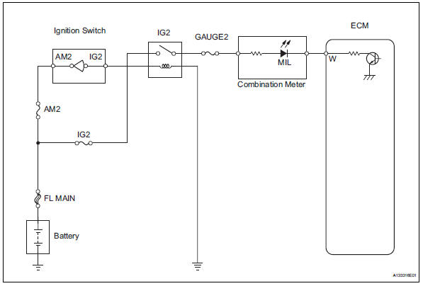
Inspection procedure
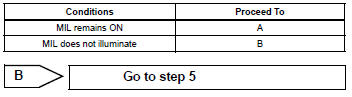
- Check that mil is illuminated
- Perform troubleshooting in accordance with the table below.

- Check whether mil turns off
- Connect the intelligent tester to the dlc3.
- Turn the ignition switch on and turn the tester on.
- Select the following menu items: diagnosis / enhanced obd ii / dtc info / current codes.
- Check if any dtcs have been stored. Note down any dtcs.
- Clear dtcs (see page es-35).
- Check if the mil goes off.
Standard: mil should go off.

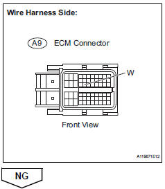
- Check harness and connector (check for short in wire harness)
- Disconnect the a9 ecm connector.
- Turn the ignition switch on.
- Check that the mil is not illuminated.
Ok: mil is not illuminated.
- Reconnect the ecm connector.
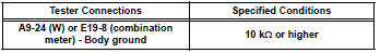
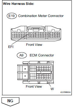
- Check harness and connector (combination meter - ecm)
- Disconnect the a9 ecm connector.
- Disconnect the e19 combination meter connector.
- Measure the resistance.
Standard resistance (check for short)
- Reconnect the ecm connector.
- Reconnect the combination meter connector.
- Check that mil is illuminated
- Check if the mil is illuminated when the ignition switch is turned on.
Ok: mil should be illuminated.

- Check that engine starts
- Turn the ignition switch on.
- Start the engine.
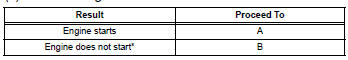
Hint:
*: The intelligent tester cannot communicate with the ecm.

- Inspect combination meter assembly (mil circuit)
- Check the mil circuit (see page me-15).

![]()
 Fuel pump control circuit
Description
When the engine is cranked, the starter relay drive signal output from the
star terminal of the ecm is
input into the sta terminal of the ecm, and ne signal generated by the
cranksha ...
 Mass air flow meter
Components
...
Other materials:
Diagnostic trouble code chart
If a dtc is displayed during the dtc check, check the circuit
listed for the dtc in the table below (refer to the appropriate
page).
Hint:
When the srs warning light remains on and the normal
system code is output, a decrease in the source voltage is
likely to occur. This malfunction is n ...
Registration
Hint:
The key has 2 codes: the key code (immobiliser code) and
the wireless code (recognition code). Both of these codes
need to be registered. For wireless code registration
procedures, refer to the following procedures (see page dl-
46). For key code registration procedures, refer to the
pro ...
Passenger side buckle switch circuit malfunction
Description
The passenger side buckle switch circuit consists of the occupant
classification ecu and the front seat
inner belt rh.
Dtc b1771 is recorded when a malfunction is detected in the passenger side
buckle switch circuit.
Troubleshoot dtc b1771 first when dtcs b1771 and b1795 ...
