Toyota RAV4 (XA40) 2013-2018 Service Manual: Throttle / pedal position sensor
Hint:
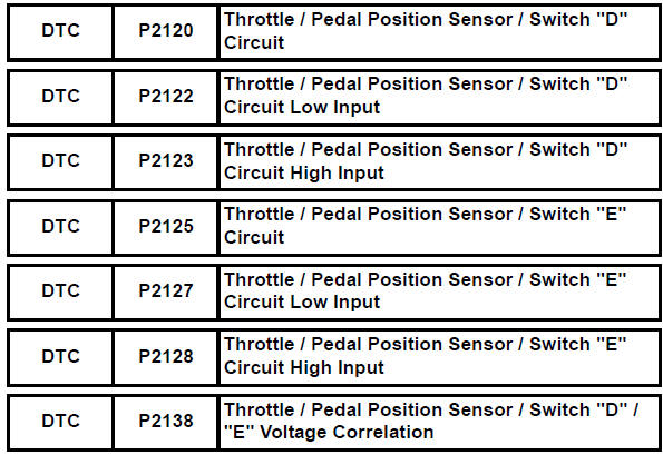
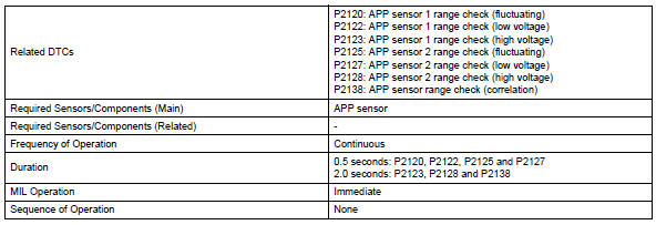
These dtcs relate to the accelerator pedal position (app) sensor.
Description
Hint:
This etcs (electronic throttle control system) does not use a throttle cable.
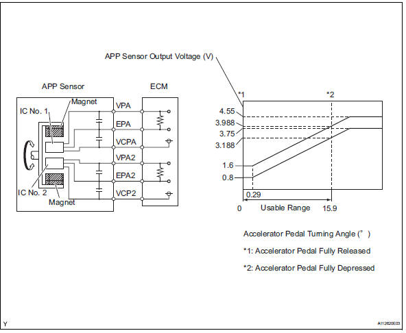
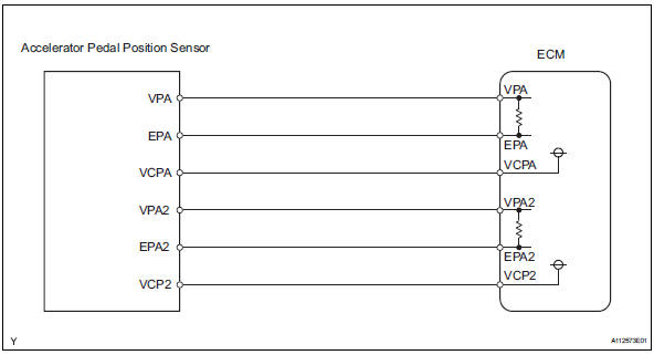
The app sensor is mounted on the accelerator pedal bracket and has 2 sensor circuits: vpa (main) and vpa2 (sub). This sensor is a non-contact type it uses hall-effect elements in order to yield accurate signals even in extreme driving conditions, such as at high speeds as well as very low speeds. The voltage, which is applied to terminals vpa and vpa2 of the ecm, varies between 0 v and 5 v in proportion to the operating angle of the accelerator pedal (throttle valve). A signal from vpa indicates the actual accelerator pedal opening angle (throttle valve opening angle) and is used for engine control. A signal from vpa2 conveys the status of the vpa circuit and is used to check the app sensor itself.
The ecm monitors the actual accelerator pedal opening angle (throttle valve opening angle) through the signals from vpa and vpa2, and controls the throttle actuator according to these signals.
Hint:
When any of these dtcs are set, check the app sensor voltage by selecting the following menu items on the intelligent tester: diagnosis / enhanced obd ii / data list / primary / accel pos #1 and accel pos #2.
Hint:
- Accelerator pedal positions are expressed as voltages.
- Ap denotes for accelerator pedal.
Monitor description
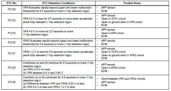
When either output voltage of vpa or vpa2 deviates from the standard range, or the difference between the output voltages of the 2 sensor circuits is less than the threshold, the ecm determines that there is a malfunction in the app sensor. The ecm then illuminates the mil and sets a dtc.
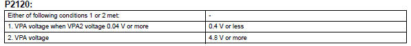
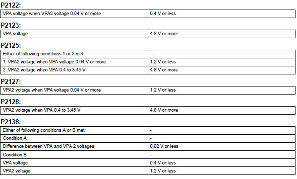
Example: when the output voltage of vpa drops below 0.4 V for more than 0.5 Seconds when the accelerator pedal is fully depressed, dtc p2122 is set.
If the malfunction is not repaired successfully, a dtc is set 2 seconds after the engine is next started.
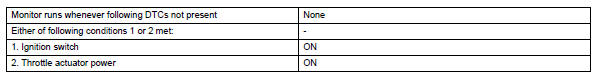
Monitor strategy
Typical enabling conditions
Typical malfunction thresholds
Component operating range

Fail-safe
When any of dtcs p2120, p2121, p2122, p2123, p2125, p2127, p2128 and p2138 are set, the ecm enters fail-safe mode. If either of the 2 sensor circuit malfunctions, the ecm uses the remaining circuit to calculate the accelerator pedal position to allow the vehicle to continue driving. If both of the circuits malfunction, the ecm regards the accelerator pedal as being released. As a result, the throttle valve is closed and the engine idles.
Fail-safe mode continues until a pass condition is detected, and the ignition switch is turned off.
Wiring diagram
Inspection procedure
Hint:
Read freeze frame data using the intelligent tester. Freeze frame data records the engine condition when malfunctions are detected. When troubleshooting, freeze frame data can help determine if the vehicle was moving or stationary, if the engine was warmed up or not, if the air-fuel ratio was lean or rich, and other data from the time the malfunction occurred.
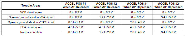
- Read value using intelligent tester (accel pos #1 and accel pos #2)
- Connect the intelligent tester to the dlc3.
- Turn the ignition switch on and turn the tester on.
- Select the following menu items: diagnosis / enhanced obd ii / data list / etcs / accel pos #1 and accel pos #2.
- Read the value displayed on the tester.
Standard voltage 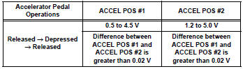


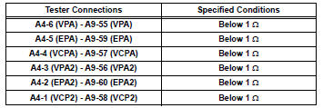
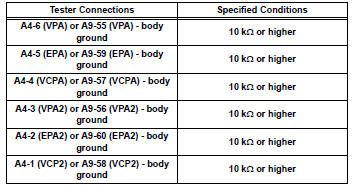
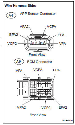
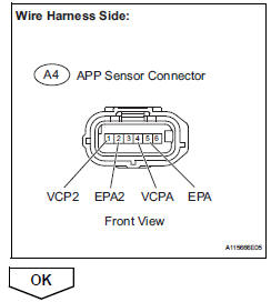
- Check harness and connector (accelerator pedal position sensor - ecm)
- Disconnect the a4 accelerator pedal position (app) sensor connector.
- Disconnect the a9 ecm connector.
- Measure the resistance.
Standard resistance (check for open)
Standard resistance (check for short)
- Reconnect the app sensor connector.
- Reconnect the ecm connector.

- Check ecm (vcpa and vcp2 voltage)
- Disconnect the a4 app sensor connector.
- Turn the ignition switch on.
- Measure the voltage between the terminals of the a4 app sensor connector.
Standard voltage 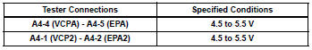
- Reconnect the app sensor connector.

- Replace accelerator pedal assembly

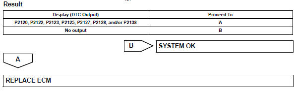
- Check whether dtc output recurs (accelerator pedal position sensor dtcs)
- Connect the intelligent tester to the dlc3.
- Turn the ignition switch on and turn the tester on.
- Clear dtcs (see page es-35).
- Start the engine
- Allow the engine to idle for 15 seconds.
- Select the following menu items: diagnosis / enhanced obd ii / dtc info / current codes.
- Read dtcs.
 Throttle actuator control throttle body range / performance
Description
The electronic throttle control system (etcs) is composed of the throttle
actuator, throttle position (tp)
sensor, accelerator pedal position (app) sensor, and ecm. The ecm operate ...
 Throttle / pedal position sensor / switch "d" circuit range / performance
Description
Hint:
Refer to dtc p2120 (see page es-282).
Monitor description
When the difference between the output voltages of vpa and vpa2 deviates from
the standard, the ecm
determines th ...
Other materials:
Installation
Hint:
Use the same procedures for the rh side and lh side.
The procedures listed below are for the lh side.
Install rear stabilizer bush
Install the 2 bushes.
Hint:
Install each bush to the outer side of the bush
stopper on each stabilizer bar.
Install each bush with ...
Removal
Disconnect cable from negative battery
terminal
Caution:
Wait at least 90 seconds after disconnecting the
cable from the negative (-) battery terminal to
prevent airbag and seat belt pretensioner activation.
Remove front seat assembly lh
Remove the front seat.
For manual sea ...
Abs warning light does not come on
Wiring diagram
Refer to the abs warning light circuit (see page bc-135).
Inspection procedure
Check can communication system
Check if the can communication system dtc is output
(see page ca-34).
Result
Perform active test by intelligent tester (abs warning light)
Sele ...
