Toyota RAV4 (XA40) 2013-2018 Service Manual: Terminals of ecu (2005/11-2006/01)
Notice:
- Turn the ignition switch off before measuring the resistances of the main wire and the branch wire.
- After the ignition switch is turned off, check that the key reminder warning system and light reminder warning system are not in operation.
- Before measuring the resistance, leave the vehicle for at least 1 minute and do not operate the ignition switch, any switches or doors. If doors need to be opened in order to check connectors, open the doors and leave them open.
Hint:
Operating the ignition switch, any switches or any doors triggers related ecu and sensor communication with the can, which causes resistance variation.
- Junction connector
- No. 1 Junction connector

-
No. 2 Junction connector

- No. 3 Junction connector


- No. 4 Junction connector


Hint:
*: For 4wd
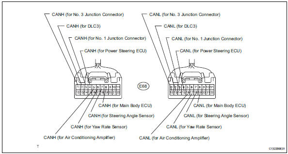
- Check dlc3

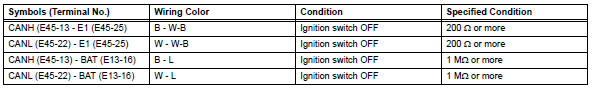
- Measure the resistance of the connector.

- Check abs and traction actuator (skid control ecu)

- Disconnect the a19 ecu connector.
- Measure the resistance of the wire harness side connector.

- Check steering angle sensor

- Disconnect the e11 sensor connector.
- Measure the resistance of the wire harness side connector.

- Check yaw rate sensor

- Disconnect the k6 sensor connector.
- Measure the resistance of the wire harness side connector.

- Check air conditioning amplifier (for automatic air conditioning system)

- Disconnect the e37 amplifier connector.
- Measure the resistance of the wire harness side connector.

- Check air conditioning amplifier (for manual air conditioning system)

- Disconnect the e36 amplifier connector.
- Measure the resistance of the wire harness side connector.


- Check ecm

- Disconnect the a19 and b30 ecm connectors.
- Measure the resistance of the wire harness side connectors.

- Check center airbag sensor assembly

- Disconnect the e45 sensor connector.
- Measure the resistance of the wire harness side connectors.

- Check power steering ecu

- Disconnect the a1 and e18 ecu connectors.
- Measure the resistance of the wire harness side connectors.

- Check combination meter ecu

- Disconnect the e19 ecu connector.
- Measure the resistance of the wire harness side connector.

- Check instrument panel junction block (main body ecu)


- Disconnect the 1b and 1e junction block connectors.
- Disconnect the e17 ecu connector.
- Measure the resistance of the wire harness side connectors.

- Check 4wd control ecu (for 4wd)
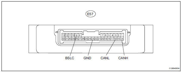
- Disconnect the e57 ecu connector.
- Measure the resistance of the wire harness side connector.

 Problem symptoms table
(2005/11-2006/01)
(2006/01- )
Hint:
*: For 4wd ...
 Check 4wd control ecu (for 4wd)
Notice:
Turn the ignition switch off before measuring the
resistances of the main wire and branch wire.
After the ignition switch is turned off, check that the
key reminder warning system an ...
Other materials:
On-vehicle inspection
Check ignition coil assembly and perform spark test
Notice:
in this section, the terms "cold" and "hot" refer to
the temperature of the coils. "Cold" means
approximately -10 to 50°c (14 to 122°f). "Hot" means
approximately 50 to 100°c (122 to 212 ...
Canceling and resuming
the speed control
Pressing the cancel switch
cancels the speed control.
The speed control is also canceled
when the brake pedal is depressed.
(When the vehicle has been
stopped by system control,
depressing the brake pedal does
not cancel the setting.)
Pressing the "+RES" switch
resumes the cruise control
a ...
Stop light switch circuit
Description
When the stop light switch is turned on, current flows to the stop lights to
illuminate them.
Wiring diagram
Inspection procedure
Inspect fuse (stop)
Remove the stop fuse from the instrument panel
junction block.
Measure the resistance of the fuse.
Standard resi ...
