Toyota RAV4 (XA40) 2013-2018 Service Manual: Tc and cg terminal circuit
Description
Connecting terminals tc and cg of the dlc3 causes the skid control ecu to display 2-digit dtcs by flashing the abs warning light.
Wiring diagram

Inspection procedure
- Check dlc3 (tc voltage)

- Turn the ignition switch on.
- Measure the voltage of the dlc3.
Standard voltage 


- Check can communication system
- Check the dtc (see page ca-34).
Result 


Replace abs and traction actuator assembly
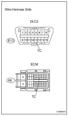
- Check wire harness (dlc3 - ecm and body ground)
- Turn the ignition switch off.
- Disconnect the a12 ecm connector.
- Measure the resistance of the wire harness side connectors.
Standard resistance 


- Check wire harness (dlc3 - body ground)
- Measure the resistance of the dlc3.
Standard resistance 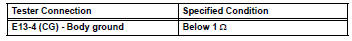


- Check can communication system
- Check if the can communication dtc is output (see page ca-34).
Result 


Replace abs and traction actuator assembly
 Skid control buzzer circuit
Description
The skid control buzzer sounds while the vsc is activated.
Wiring diagram
Inspection procedure
Notice:
When replacing the abs and traction actuator, perform the zero point
calib ...
 Ts and cg terminal circuit
Description
If the vehicle is stationary during sensor check mode, speed sensor
malfunctions cannot be detected. The
vehicle must be driven for speed sensor malfunctions to be detected.
Hint:
...
Other materials:
Automatic transaxle assembly
Components
Removal
Remove engine assembly with transaxle
Remove the engine with transaxle (see page em-
98).
Drain automatic transaxle fluid
Remove the drain plug and gasket, and drain atf.
Install a new gasket and the drain plug.
Torque: 47 n*m (479 kgf*cm, 35 ft. ...
Multi-terrain Select (AWD
vehicles)
Multi-terrain Select is
designed to control AWD,
brake and driving force systems
in accordance with the
road condition. Use the system
when driving over
muddy, sandy or rough road
surfaces.
WARNING
â– Before using Multi-terrain
Select
Make sure to observe the following
precautions. Failure to
observ ...
Light bulbs
You may replace the following
bulbs by yourself. The
difficulty level of replacement
varies depending on
the bulb. If necessary bulb
replacement seems difficult
to perform, contact your
Toyota dealer.
For more information about
replacing other light bulbs,
contact your Toyota dealer.
Preparing for ...
