Toyota RAV4 (XA40) 2013-2018 Service Manual: Short in front passenger side - side squib circuit
Description
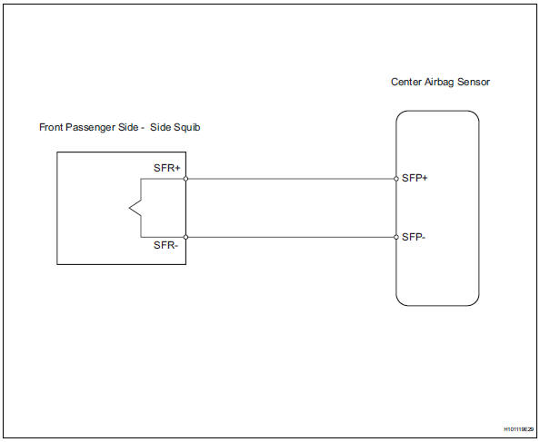
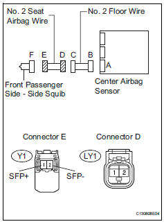
The front passenger side - side squib circuit consists of the center airbag sensor and the front seat side airbag rh.
The circuit instructs the srs to deploy when the deployment conditions are met.
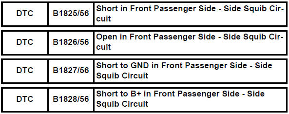
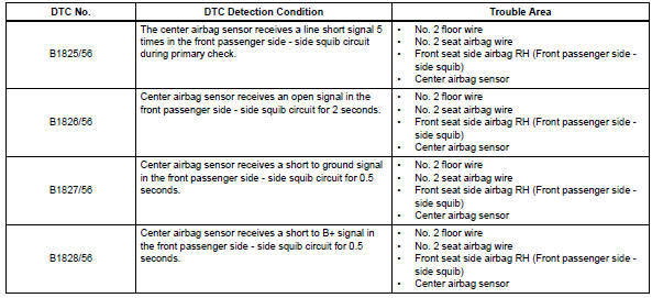
These dtcs are recorded when a malfunction is detected in the front passenger side - side squib circuit.
Wiring diagram
Inspection procedure
Hint:
- Perform the simulation method by selecting the "check mode" (signal check) with the intelligent tester (see page rs-52).
- After selecting the "check mode" (signal check), perform the simulation method by wiggling each connector of the airbag system or driving the vehicle on a city or rough road (see page rs-52).
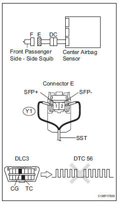
- Check front seat side airbag assembly rh (front passenger side - side squib)
- Turn the ignition switch off.
- Disconnect the cable from the negative (-) battery terminal, and wait for at least 90 seconds.
- Disconnect the connector from the front seat side airbag rh.
- Connect the black wire side of sst to connector c.
Caution:
Never connect a tester to the front seat side airbag rh (front passenger side - side squib) for measurement, as this may lead to a serious injury due to airbag deployment.
Notice:
- Do not forcibly insert sst into the terminals of the connector when connecting.
- Insert sst straight into the terminals of the connector.
Sst 09843-18060
- Connect the cable to the negative (-) battery terminal, and wait for at least 2 seconds.
- Turn the ignition switch on, and wait for at least 60 seconds.
- Clear the dtcs (see page rs-49).
- Turn the ignition switch off
- Turn the ignition switch on, and wait for at least 60 seconds.
- Check the dtcs (see page rs-49).
Ok: dtc b1825, b1826, b1827, b1828 or 56 is not output.
Hint:
Dtcs other than dtc b1825, b1826, b1827, b1828 or 56 may be output at this time, but they are not related to this check.

- Check connector
- Turn the ignition switch off.
- Disconnect the cable from the negative (-) battery terminal, and wait for at least 90 seconds.
- Disconnect sst from connector e.
- Check that the no. 2 Seat airbag wire connectors (on the front passenger side - side squib) are not damaged.
Ok: lock button is not disengaged, and claw of lock is not deformed or damaged.

- Check no. 2 Floor wire (front passenger side - side squib circuit)
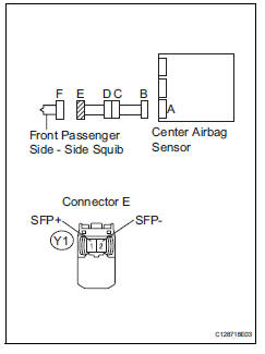
- Disconnect the connector from the center airbag sensor.
- Connect the cable to the negative (-) battery terminal, and wait for at least 2 seconds.
- Turn the ignition switch on.
- Measure the voltage of the wire harness side connector.
Standard voltage 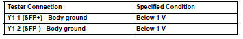
- Turn the ignition switch off
- Disconnect the cable from the negative (-) battery terminal, and wait for at least 90 seconds.
- Measure the resistance of the wire harness side connector.
Standard resistance 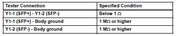
- Release the activation prevention mechanism built into connector b (see page rs-37).
- Measure the resistance of the wire harness side connector.
Standard resistance 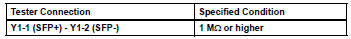

- Check no. 2 Seat airbag wire
- Disconnect the no. 2 Seat airbag wire from the no. 2 Floor wire.
- Connect the cable to the negative (-) battery terminal, and wait for at least 2 seconds.
- Turn the ignition switch off.
- Measure the voltage of the wire harness side connector.
Standard voltage 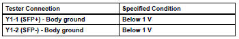
- Turn the ignition switch off.
- Disconnect the cable from the negative (-) battery terminal, and wait for at least 90 seconds
- Measure the resistance of the wire harness side connector.
Standard resistance 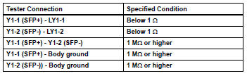

Repair or replace no. 2 Floor wire
 Short in front driver side - side squib circuit
Description
The driver side - side squib circuit consists of the center airbag sensor and
the front seat side airbag lh.
This circuit instructs the srs to deploy when the deployment conditio ...
 Short in driver side curtain shield squib circuit
Description
The driver side curtain shield squib circuit consists of the center airbag
sensor and the curtain shield
airbag lh.
The circuit instructs the srs to deploy when the deployment c ...
Other materials:
Auto lsd indicator light remains on
Description
This is the auto lsd switch for 2wd. When the auto lsd switch is pushed on,
the auto lsd function is
available and the auto lsd indicator light illuminates.
Hint:
The auto lsd does not operate even if the auto lsd switch is pressed under
the following conditions:
The trc or v ...
Dtc check / clear
Check dtc
Connect the intelligent tester (with can vim) to the
dlc3.
Turn the ignition switch on and turn the intelligent
tester on.
Read the dtc by following the prompts on the
tester screen.
Hint:
Refer to the intelligent tester operator's manual for
further details.
...
Air outlet damper control servo motor circuit
Description
The damper servo sends pulse signals to indicate the damper position to the
air conditioning amplifier.
The air conditioning amplifier activates the motor (normal or reverse) based on
these signals to move the
mode damper to the appropriate position, which controls the air o ...
