Toyota RAV4 (XA40) 2013-2018 Service Manual: Short in front passenger side pretensioner squib circuit

Description
The front passenger side front pretensioner squib circuit consists of the center airbag sensor and the front seat outer belt rh.
This circuit instructs the srs to deploy when the deployment conditions are met.
These dtcs are recorded when a malfunction is detected in the front passenger side front pretensioner squib circuit.

Wiring diagram

Inspection procedure
Hint:
- Perform the simulation method by selecting the "check mode" (signal check) with the intelligent tester (see page rs-52).
- After selecting the "check mode" (signal check), perform the simulation method by wiggling each connector of the airbag system or driving the vehicle on a city or rough road (see page rs-52).
- Check front seat outer belt assembly rh (front passenger side front pretensioner squib)

- Turn the ignition switch off.
- Disconnect the cable from the negative (-) battery terminal, and wait for at least 90 seconds.
- Disconnect the connectors from the front seat outer belt rh.
- Connect the white wire side of sst to connector c.
Caution:
Never connect a tester to the front seat outer belt rh (front passenger side front pretensioner squib) for measurement, as this may lead to a serious injury due to airbag deployment.
Notice:
- Do not forcibly insert sst into the terminals of the connector when connecting.
- Insert sst straight into the terminals of the connector.
Sst 09843-18060
- Connect the cable to the negative (-) battery terminal, and wait for at least 2 seconds.
- Turn the ignition switch on, and wait for at least 60 seconds.
- Clear the dtcs (see page rs-49).
- Turn the ignition switch off.
- Turn the ignition switch on, and wait for at least 60 seconds
- Check the dtcs (see page rs-49).
Ok: dtc b1905, b1906, b1907, b1908 or 74 is not output.
Hint:
Dtcs other than dtc b1905, b1906, b1907, b1908 or 74 may be output at this time, but they are not related to this check.


- Check con3
- Turn the ignition switch off.
- Disconnect the cable from the negative (-) battery terminal, and wait for at least 90 seconds.
- Disconnect sst from connector c.
- Check that the floor wire connector (on the front seat outer belt rh side) is not damaged.
Ok: lock button is not disengaged, or the claw of the lock is not deformed or damaged.


- Check floor wire (front passenger side front pretensioner squib circuit)

- Disconnect the connectors from the center airbag sensor.
- Connect the cable to the negative (-) battery terminal, and wait for at least 2 seconds.
- Measure the voltage of the wire harness side connector.
Standard voltage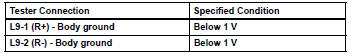
- Turn the ignition switch off.
- Disconnect the cable from the negative (-) battery terminal, and wait for at least 90 seconds.
- Measure the resistance of the wire harness side connector.
Standard resistance 
- Release the activation prevention mechanism built into connector b (see page rs-37).
- Measure the resistance of the wire harness side connector.
Standard resistance 


Replace center airbag sensor assembly
 Short in front driver side pretensioner squib circuit
Description
The driver side front pretensioner squib circuit consists of the center
airbag sensor and the front seat
outer belt lh.
This circuit instructs the srs to deploy when the deploym ...
 Source voltage drop
Description
The srs is equipped with a voltage-increase circuit (dc-dc converter) in the
center airbag sensor in
case the source voltage drops.
When the source voltage drops, the voltage-increa ...
Other materials:
Brk relay
On-vehicle inspection
Inspect brk relay
Remove the brk relay from the engine room no. 1
Relay block.
Measure the resistance of the relay.
Standard resistance
If the result is not as specified, replace the relay. ...
Using an anchor bracket
(for top tether strap)
â– Anchor brackets (for top
tether strap)
Anchor brackets are provided
for each rear seat.
Use anchor brackets when fixing
the top tether strap.
Outboard rear seats
Anchor brackets
Top tether strap
Center rear seat
Anchor bracket
Top tether strap
â– Fixing the top tether strap
to the an ...
Rear occupant classification sensor lh circuit malfunction
Description
The rear occupant classification sensor lh circuit consists of the occupant
classification ecu and the rear
occupant classification sensor lh.
Dtc b1782 is recorded when a malfunction is detected in the rear occupant
classification sensor lh
circuit.
Wiring diagram
...
