Toyota RAV4 (XA40) 2013-2018 Service Manual: Room temperature sensor circuit
![]()
Description
The room temperature sensor is installed in the instrument panel to detect the room temperature and control the heater and air conditioner auto mode. The resistance of the room temperature sensor changes in accordance with the room temperature. As the temperature decreases, the resistance increases. As the temperature increases, the resistance decreases.
The air conditioning amplifier applies a voltage (5 v) to the room temperature sensor and reads voltage changes as changes in the resistance of the room temperature sensor.

Wiring diagram

Inspection procedure
- Read value of intelligent tester (room temp)
- Connect the intelligent tester (with can vim) to the dlc3.
- Turn the ignition switch on and turn the intelligent tester main switch on.
- Select the item below in the data list, and read the value displayed on the intelligent tester.

Ok: the display is as specified in the normal condition column.


- Inspect cooler thermistor (room temperature sensor)

- Remove the room temperature sensor.
- Measure the resistance of the sensor.
Standard resistance 
Notice:
- Touching the sensor even slightly may change the resistance value. Be sure to hold the connector of the sensor.
- When measuring, the sensor temperature must be the same as the ambient temperature.
Hint:
As the temperature increases, the resistance decreases (see the graph).

- Check wire harness (room temperature sensor - air conditioning amplifier)

- Disconnect the e21 sensor connector.
- Disconnect the e37 amplifier connector.
- Measure the resistance of the wire harness side connectors.
Standard resistance 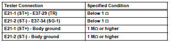


Replace air conditioning amplifier assembly
 Diagnostic trouble code chart (2006/01- )
Hint:
When the air conditioning system functions properly, dtc
b1400/00 is output.
Hint:
*1: Dtc b1422/22 (compressor lock sensor circuit) is
indicated only for a currently occurring malf ...
 Ambient temperature sensor circuit
Description
The ambient temperature sensor is installed in the front part of the
condenser to detect the ambient
temperature and control the air conditioner. The sensor is connected to the
c ...
Other materials:
Installation
Install tire pressure warning antenna and receiver
Install the receiver with the bolt.
Torque: 7.5 N*m (76 kgf*cm, 66 in.*Lbf)
Connect the connector.
Install inner roof side garnish assembly
rh (see page ir-52)
Install deck trim side panel assembly rh
(w/o rear no. 2 S ...
Manual air conditioning system
Air conditioning controls
Fan speed control switch
Temperature control switch
On/off switch
Windshield defogger switch
Rear window and outside rear view mirror defoggers* switch
Airflow mode control switch
Outside/recirculated air mode switch
"A/C" switch
"MAX A/C" switch
*: If equipped
...
Evaporative emission control system leak detected
Dtc summary
Description
The description can be found in the evap (evaporative emission) system (see
page es-335).
Inspection procedure
Refer to the evap system (see page es-340).
Monitor description
5 Hours* after the ignition switch is turned off, the leak detection pump
creates n ...
