Toyota RAV4 (XA40) 2013-2018 Service Manual: Evaporative emission control system leak detected
Dtc summary
Description
The description can be found in the evap (evaporative emission) system (see page es-335).
Inspection procedure
Refer to the evap system (see page es-340).
Monitor description
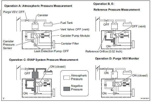
5 Hours* after the ignition switch is turned off, the leak detection pump creates negative pressure (vacuum) in the evap system. The ecm monitors for leaks and actuator malfunctions based on the evap pressure.
Hint:
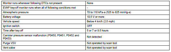
*: If the engine coolant temperature is not below 35°c (95°f) 5 hours after the ignition switch is turned off, the monitor check starts 2 hours later. If it is still not below 35°c (95°f) 7 hours after the ignition switch is turned off, the monitor check starts 2.5 Hours later.
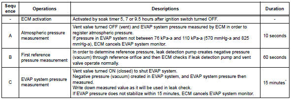
*: If only a small amount of fuel is in the fuel tank, it takes longer for the evap pressure to stabilize.
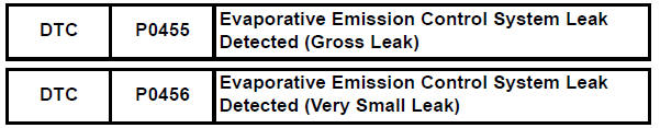
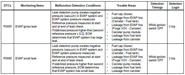
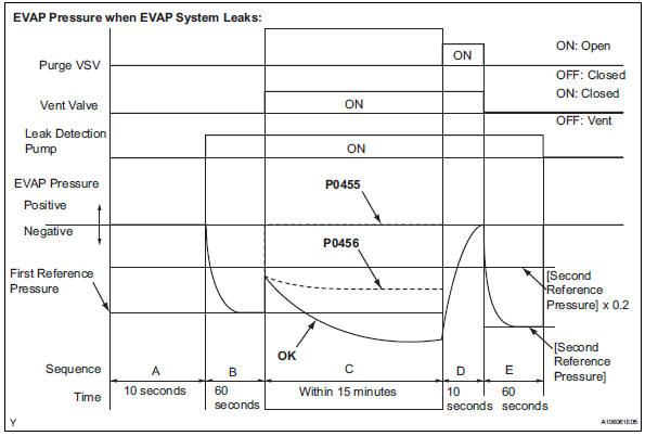
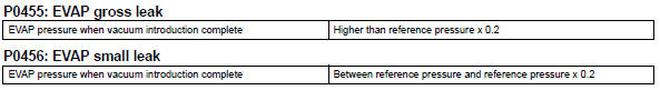
- P0455: evap gross leak
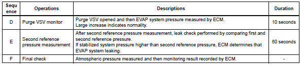
In operation c, the leak detection pump creates negative pressure (vacuum) in the evap system and the evap system pressure is measured. If the stabilized system pressure is higher than [second reference pressure x 0.2] (Near atmospheric pressure), the ecm determines that the evap system has a large leakage, illuminates the mil and sets the dtc (2 trip detection logic).
- P0456: evap very small leak
In operation c, the leak detection pump creates negative pressure (vacuum) in the evap system and the evap system pressure is measured. If the stabilized system pressure is higher than the second reference pressure, the ecm determines that the evap system has a small leakage, illuminates the mil and sets the dtc (2 trip detection logic).
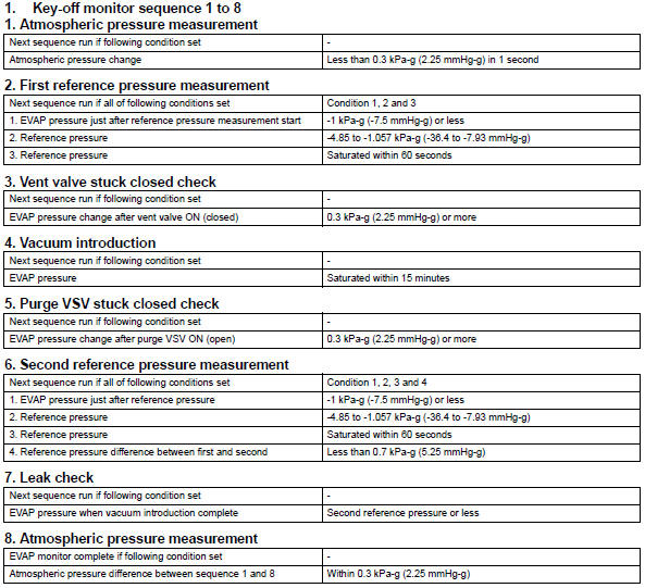
Monitor strategy
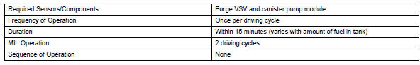
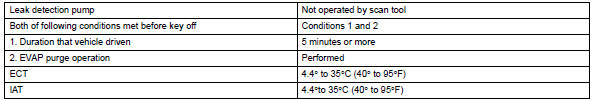
Typical enabling conditions
Typical malfunction thresholds
Monitor result
Refer to checking monitor status (see page es-17).
 Evaporative emission control system pressure sensor
Dtc summary
Hint:
The canister pressure sensor is built into the canister pump module.
Description
The description can be found in the evap (evaporative emission) system (see
page es ...
 Vehicle speed sensor "A"
description
The speed sensor detects the wheel speed and sends the appropriate signals to
the skid control ecu.
The skid control ecu converts these wheel speed signals into a 4-pulse signal ...
Other materials:
Data list / active test (2006/01- )
Read data list
Hint:
Using the intelligent tester's data list allows switch,
sensor, actuator and other item values to be read without
removing any parts. Reading the data list early in
troubleshooting is one way to save time.
Connect the intelligent tester (with can vim) to the
...
How to proceed with troubleshooting (2006/01- )
Hint:
Use these procedures to troubleshoot the air conditioning
system.
*: Use the intelligent tester.
Vehicle brought to workshop
Customer problem analysis and symptom check
Inspect battery voltage
Standard voltage:
11 to 14 v
If the voltage is below 11 v, recharg ...
Parts location
System diagram
...
