Toyota RAV4 (XA40) 2013-2018 Service Manual: Pressure control solenoid "d" performance (shift solenoid valve slt)

Description

The throttle pressure that is applied to the primary regulator valve (which modulates the line pressure) causes the solenoid valve slt, under electronic control, to precisely modulate and generate the line pressure according to the extent that the accelerator pedal is depressed or the output of engine power.
This controls the line pressure and provides smooth shifting characteristics.
Upon receiving a signal of the throttle valve opening angle, the ecm controls the line pressure by sending a predetermined duty ratio* to the solenoid valve, modulating the line pressure and generating throttle pressure.
Hint:
*: The duty ratio is the ratio of the current on time (a) to the total of the current on and off time (a + b).
Duty ratio (%) = a / (a + b) x 100

Monitor description
In any forward position, when the difference between the revolutions of the turbine and output shaft exceeds the specified value (varies with output speed) determined by the ecm, the ecm illuminates the mil and outputs the dtc. When shift solenoid valve slt remains on, the oil pressure goes down and the clutch engagement force decreases.
Monitor strategy

Typical enabling conditions
The following conditions are common to on malfunctions (a), (b), (c) and (d).

Typical malfunction thresholds
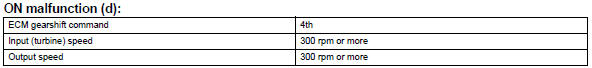
[On malfunction]
Detection condition: total accumulated time of on malfunctions (a), (b), (c) and (d) is 1 second or more

Wiring diagram

Inspection procedure
Hint:
Performing the intelligent tester's active test allows relay, vsv, actuator and other items to be operated without removing any parts. Performing the active test early in troubleshooting is one way to save time.
The data list can be displayed during the active test.
- Warm up the engine.
- Turn the ignition switch off.
- Connect the intelligent tester to the can vim. Then connect the can vim to the dlc3.
- Turn the ignition switch on and turn the tester on.
- Enter the following menus: diagnosis / enhanced obd ii / active test.
- Perform the active test

Hint:
*: "Solenoid (slt)" in the active test is performed to check the line pressure changes by connecting sst to the automatic transaxle, which is used in the hydraulic test (see page ax-16) as well. Please note that the pressure values in the active test and hydraulic test are different.
- Check other dtcs output (in addition to dtc p2714)
- Connect the intelligent tester to the can vim. Then connect the can vim to the dlc3.
- Turn the ignition switch on and turn the tester on.
- Enter the following menus: diagnosis / enhanced obd ii / dtc info / current codes.
- Read the dtcs using the tester.
Result
Hint:
If any other codes besides p2714 are output, perform troubleshooting for those dtcs first.


- inspect shift solenoid valve slt

- Remove the shift solenoid valve slt.
- Measure the resistance of the solenoid valve.
Standard resistance: 5.0 To 5.6 Ùat 20°c (68°f)
- Connect the battery's positive (+) lead with a 21 w bulb to terminal 2 and the negative (-) lead to terminal 1 of the solenoid valve connector. Then check that the valve moves and makes an operating noise.
Ok: valve moves and makes operating noise.


- Inspect transmission valve body assembly
- Check the transmission valve body assembly.
Ok: there are no foreign objects on each valve.


- Inspect torque converter clutch assembly
- Check the torque converter clutch assembly (see page ax-153).
Ok: the torque converter clutch operates normally.


Repair or replace automatic transaxle assembly
 Shift solenoid "d" control circuit
Description
Shifting from 1st to o/d is performed in combination with the on and off
operation of the shift solenoid
valves sl1 and sl2, which are controlled by the ecm. If an open or short ci ...
 Pressure control solenoid "d" electrical (shift solenoid valve slt)
Description
Refer to dtc p2714 (see page ax-91).
Monitor description
When an open or short in the shift solenoid valve slt circuit is detected,
the ecm interprets this as a fault.
The ...
Other materials:
Evaporative emission control system leak detected
Dtc summary
Description
The description can be found in the evap (evaporative emission) system (see
page es-335).
Inspection procedure
Refer to the evap system (see page es-340).
Monitor description
5 Hours* after the ignition switch is turned off, the leak detection pump
creates n ...
Removal
Drain engine coolant (see page co-6)
Disconnect cable from negative battery
terminal
Caution:
Wait at least 90 seconds after disconnecting the
cable from the negative (-) battery terminal to
prevent airbag and seat belt pretensioner activation.
Remove air cleaner cap (see page es-41 ...
Check for intermittent problems
Check for intermittent problems
Hint:
A momentary interruption (open circuit) in the connectors
and/or wire harness between the sensors and ecus can
be detected by using the ecu data list function of an
intelligent tester.
Turn the ignition switch off and connect the
intelligent test ...
