Toyota RAV4 (XA40) 2013-2018 Service Manual: Installation (2006/01- )
- Install front drive shaft assembly lh
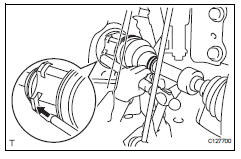
- Coat the spline of the inboard joint shaft with gear oil.
- Align the shaft splines and tap in the drive shaft with a brass bar and hammer.
Notice:
- Set the snap ring with the opening side facing downwards.
- Be careful not to damage the oil seal, boot and dust cover.
- Install front drive shaft assembly rh
- Coat the spline of the inboard joint shaft with gear oil.
- Align the shaft splines and securely insert the drive shaft
Notice:
Do not damage the oil seal.
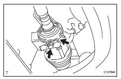
- Squeeze the ends of the bracket hole snap ring and install it to the bearing bracket.
- Install the bearing bracket bolt.
Torque: 32.4 N*m (330 kgf*cm, 24 ft.*Lbf)
- Connect steering knuckle with axle hub lh
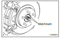
- Align the shaft splines in the drive shaft to the steering knuckle with axle hub, and connect the steering knuckle with axle hub.
- Connect steering knuckle with axle hub rh
Hint:
Use the same procedures described for the lh side.
- Connect front suspension lower no. 1 Arm sub-assembly lh (see page sp-24)
- Connect front suspension lower no. 1 Arm sub-assembly rh
Hint:
Use the same procedures described for the lh side.
- Install front stabilizer link assembly lh (see page sp-31)
- Install front stabilizer link assembly rh
Hint:
Use the same procedures described for the lh side.
- Install tie rod end sub-assembly lh (see page ps-45)
- Install tie rod end sub-assembly rh
Hint:
Use the same procedures described for the lh side.
- Connect front speed sensor lh
- Connect the speed sensor (see page bc-193).
- Connect front speed sensor rh
Hint:
Use the same procedures described for the lh side.
- Install front axle hub nut (see page ah-11)
- Install front wheel torque: 103 n*m (1,050 kgf*cm, 76 ft.*Lbf)
- Add automatic transaxle fluid
- Add automatic transaxle fluid for u140f (see page ax-152).
- Add automatic transaxle fluid for u241e (see page ax-151).
- Add automatic transaxle fluid for u151f (see page ax-178).
- Check for automatic transaxle fluid leakage
- Inspect and adjust front wheel alignment
- Inspect and adjust the front wheel alignment (see page sp-3).
 Installation
(2005/11-2006/01)
Installation
(2005/11-2006/01)
Install front drive shaft assembly lh
Coat the spline of the inboard joint shaft with gear
oil.
Using a brass bar and hammer, align the shaft
splines in the drive shaft.
Notice:
...
 Rear drive shaft assembly
Components
Removal
Hint:
Use the same procedures for the rh side and lh side.
The procedures listed below are for the lh side.
Disconnect cable from negative battery
terminal
Ca ...
Other materials:
Replacement
discharge refrigerant from refrigeration system
Start up the engine.
Turn the a/c switch on.
Operate the cooler compressor with an engine
speed of approximately 1,000 rpm for 5 to 6 minutes
to circulate the refrigerant and collect the
compressor oil remaining in each component int ...
Exhaust pipe
Installation
Install front exhaust pipe assembly
Using a vernier caliper, measure the free length of
the compression spring.
Minimum length:
41.5 Mm (1.634 In.)
If the length is less than the minimum, replace the
compression spring.
Install a new gasket by hand so that its ...
Precaution
If any of following conditions are met,
keep engine idling with a/c on (engine
speed at less than 2000 rpm) for at least 1
minute:
Refrigerant gas has been refilled or a/c parts have
been replaced.
A long time has elapsed since the engine was
stopped.
Notice:
If the engine s ...
