
Toyota RAV4 (XA40) 2013-2018 Service Manual: Installation
Hint:
A bolt without a torque specification is shown in the standard bolt chart (see page ss-2).
- Install front seat inner belt assembly (for power seat)
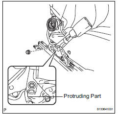
- Install the front seat inner belt assembly with the nut.
Torque: 42 n*m (428 kgf*cm, 31 ft.*Lbf)
Notice:
Do not overlap the anchor part of the seat belt and protruding part of the seat adjuster.
- For driver seat: attach the 2 clamps and connect the 2 connector.
- For passenger seat: attach the clamp and connect the 2 connector.
- Install front seat inner belt assembly (for manual seat)
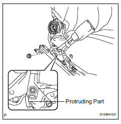
- Install the front seat inner belt assembly with the nut.
Torque: 42 n*m (428 kgf*cm, 31 ft.*Lbf)
Notice:
Do not overlap the anchor part of the seat belt and protruding part of the seat adjuster.
- For driver seat: attach the 3 clamps and connect the 2 connector.
- For passenger seat: attach the 2 clamps and connect the connector.
- Install front seat cushion inner shield lh (see page se-21)
- Install front seat cushion inner shield rh (see page se-21)
- Install front seat assembly (for power seat) (see page se-27)
- Install front seat assembly (for manual seat) (see page se-11)
- Install front seat track bracket outer cover lh (see page se-23)
- Install front seat track bracket inner cover lh (see page se-23)
- Install front seat track bracket inner cover rh
- Use the same procedures described for the lh side.
- Install front seat track bracket outer cover rh
- Use the same procedures described for the lh side.
- Connect cable to negative battery terminal
 Removal
Disconnect cable from negative battery
terminal
Caution:
Wait at least 90 seconds after disconnecting the
cable from the negative (-) battery terminal to
prevent airbag and seat belt preten ...

Other materials:
Exhaust gas precautions
Harmful substance to the
human body is included in
exhaust gases if inhaled.
WARNING
Exhaust gases contain harmful
carbon monoxide (CO), which is
colorless and odorless. Observe
the following precautions.
Failure to do so may cause
exhaust gases to enter the vehicle
and may lead to an accident
caus ...
Disassembly
Hint:
When removing the ornament plate and emblem, heat the
radiator grille, ornament plate and emblem using a heat light.
Standard heating temperature
Notice:
Do not heat the emblem base and emblem excessively.
Remove hood to radiator grille seal
Remove the double-side tape.
Deta ...
Traction control switch (for 2wd)
Components
Removal
Disconnect cable from negative battery
terminal
Caution:
Wait at least 90 seconds after disconnecting the
cable from the negative (-) battery terminal to
prevent airbag and seat belt pretensioner activation.
Remove traction control switch (auto lsd switch)
...
