Toyota RAV4 (XA40) 2013-2018 Service Manual: Front occupant classification sensor lh circuit malfunction

Description
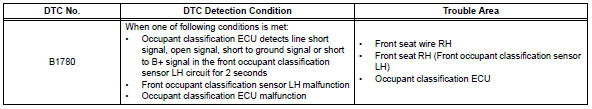
The front occupant classification sensor lh circuit consists of the occupant classification ecu and the front occupant classification sensor lh.
Dtc b1780 is recorded when a malfunction is detected in the front occupant classification sensor lh circuit.
Wiring diagram

Inspection procedure
Hint:
- If troubleshooting (wire harness inspection) is difficult to perform, remove the front passenger seat installation bolts to see the undersurface of the seat cushion.
- In the above case, hold the seat so that it does not tip over. Holding the seat for a long period of time may cause a problem, such as seat rail deformation. Hold the seat up only for as long as necessary.
- Check for dtc
- Turn the ignition switch on.
- Clear the dtcs (see page rs-249).
Hint:
First clear dtcs stored in the occupant classification ecu and then in the center airbag sensor.
- Turn the ignition switch off.
- Turn the ignition switch on.
- Check the dtcs (see page rs-249).
Ok: dtc b1780 is not output.
Hint:
Dtcs other than dtc b1780 may be output at this time, but they are not related to this check.


- Check connection of connector
- Turn the ignition switch off.
- Disconnect the cable from the negative (-) battery terminal, and wait for at least 90 seconds.
- Check that the connectors are properly connected to the occupant classification ecu and the front occupant classification sensor lh.
Ok: the connectors are properly connected.


- Check front seat wire rh (to b+)

- Disconnect the connectors from the occupant classification ecu and the front occupant classification sensor lh.
- Connect the cable to the negative (-) battery terminal, and wait for at least 2 seconds.
- Turn the ignition switch on.
- Measure the voltage of the wire harness side connector.
Standard voltage


- Check front seat wire rh (for open)

- Turn the ignition switch off.
- Disconnect the cable from the negative (-) battery terminal, and wait for at least 90 seconds.
- Using a service wire, connect terminals a2-1 (svc1) and a2-3 (sgd1), and connect terminals a2-2 (sig1) and a2- 3 (sgd1) of connector c.
Notice:
Do not forcibly insert a service wire into the terminals of the connector when connecting them.
- Measure the resistance of the wire harness side connector.
Standard resistance


- check front seat wire rh (for short)

- Disconnect the service wire from connector c.
- Measure the resistance of the wire harness side connector
Standard resistance 


- Check front seat wire rh (to ground)

- Measure the resistance of the wire harness side connector.
Standard resistance 


- Check for dtc
- Connect the connectors to the occupant classification ecu and the front occupant classification sensor lh.
- Connect the cable to the negative (-) battery terminal, and wait for at least 2 seconds.
- Turn the ignition switch on.
- Clear the dtcs (see page rs-249).
Hint:
First clear dtcs stored in the occupant classification ecu and then in the center airbag sensor.
- Turn the ignition switch off.
- Turn the ignition switch on.
- Check the dtcs (see page rs-249).
Ok: dtc b1780 is not output.
Hint:
Dtcs other than dtc b1780 may be output at this time, but they are not related to this check.


- Replace occupant classification ecu
- Turn the ignition switch off.
- Disconnect the cable from the negative (-) battery terminal, and wait for at least 90 seconds.
- Replace the occupant classification ecu (see page rs- 392).
Hint:
Perform the inspection using parts from a normal vehicle if possible.

- Perform zero point calibration
- Connect the cable to the negative (-) battery terminal, and wait for at least 2 seconds.
- Connect the intelligent tester (with can vim) to the dlc3.
- Turn the ignition switch on.
- Using the intelligent tester, perform the zero point calibration (see page rs-241).
Ok: completed is displayed.


- Perform sensitivity check
- Using the intelligent tester, perform the sensitivity check (see page rs-241).
Standard values: 27 to 33 kg (59.52 To 72.75 Lb)


- Check for dtc
- Connect the cable to the negative (-) battery terminal, and wait for at least 2 seconds.
- Turn the ignition switch on.
- Clear the dtcs (see page rs-249).
Hint:
First clear dtcs stored in the occupant classification ecu and then in the center airbag sensor.
- Turn the ignition switch off.
- Turn the ignition switch on.
- Check the dtcs (see page rs-249).
Ok: dtc b1780 is not output.
Hint:
Codes other than dtc b1780 may be output at this time, but they are not related to this check.


- Replace front seat assembly rh
- Turn the ignition switch off.
- Disconnect the cable from the negative (-) battery terminal, and wait for at least 90 seconds.
- Replace the front seat rh (see page se-11).

- Perform zero .on
- Connect the cable to the negative (-) battery terminal, and wait for at least 2 seconds.
- Connect the intelligent tester to the dlc3.
- Turn the ignition switch on.
- Using the intelligent tester, perform the zero point calibration (see page rs-241).
Ok: completed is displayed.

- Perform sensitivity check
- Using the intelligent tester, perform the sensitivity check (see page rs-241).
Standard value: 27 to 33 kg (59.52 To 72.75 Lb)

End
 Passenger side buckle switch circuit malfunction
Description
The passenger side buckle switch circuit consists of the occupant
classification ecu and the front seat
inner belt rh.
Dtc b1771 is recorded when a malfunction is detected in th ...
 Front occupant classification sensor rh circuit malfunction
Description
The front occupant classification sensor rh circuit consists of the occupant
classification ecu and the
front occupant classification sensor rh.
Dtc b1781 is recorded when a mal ...
Other materials:
Initialization
Zero point calibration
Notice:
Make sure that the front passenger seat is not
occupied before performing the operation.
Hint:
Perform the zero point calibration and sensitivity check if
any of the following conditions apply.
The occupant classification ecu is replaced.
Accessories ( ...
Rear seats
Reclining adjustments and
folding the seatbacks can
be done with lever operation.
Adjustment procedure
Pull the seatback angle adjustment
lever A, and adjust the
seatback angle.
WARNING
â– When operating the seatback
Observe the following precautions.
Failure to do so may cause death
or serious in ...
Parking brake system
Problem symptoms table
Hint:
Use the table below to help determine the cause of the
problem symptom. The potential causes of the symptoms are
listed in order of probability in the "suspected area" column of
the table. Check each symptom by checking the suspected
areas in the order th ...
