Toyota RAV4 (XA40) 2013-2018 Service Manual: Disassembly
- Remove radiator grille sub-assembly
- Remove the 4 bolts and 4 nuts.

- Detach the 6 claws and remove the radiator grille.

- Remove no. 1 Radiator grille lower
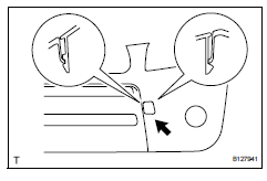
- Detach the 18 claws and remove the radiator grille.

- Remove no. 2 Radiator grille lower

- Detach the 16 claws and remove the radiator grille.
- Remove front bumper arm hole cover lh
- Detach the 2 claws and disconnect the arm hole cover.
- Remove the hook and bumper arm hole cover.
- Remove front bumper arm hole cover rh

- Use the same procedures described for the lh side.
- Remove fog light assembly lh

- Remove the screw and fog light.
- Remove the 3 bolts and fog light mounting bracket.
- Remove fog light assembly rh
Hint:
Use the same procedures described for the lh side.
- Remove front bumper hole cover lh (w/o fog light)

- Remove the 3 bolts, bumper hole cover and fog light mounting bracket.
- Remove front bumper hole cover rh (w/o fog light)
Hint:
Use the same procedures described for the lh side.
- Remove front bumper extension lh (for wide body)
- Detach the 7 outside moulding retainers and remove the extension lh.
Notice:
- If reusing the extension, take care not to damage the extension.
- Be careful not to damage the vehicle body.

- Remove front bumper extension rh (for wide body)
Hint:
Use the same procedures described for the lh side.
 Removal
Disconnect cable from negative battery
terminal
Caution:
Wait at least 90 seconds after disconnecting the
cable from the negative (-) battery terminal to
prevent airbag and seat belt preten ...
 Reassembly
V
Attach the 7 outside moulding retainers to install the
extension.
Install front bumper extension rh (for wide
body)
Hint:
Use the same procedures described for the lh side ...
Other materials:
Camshaft position correlation (bank 1 sensor a)
Dtc P0016 P0016 crankshaft position - camshaft position correlation
(bank 1 sensor a)
Description
In the vvt (variable valve timing) system, the appropriate intake valve open
and close timing is
controlled by the ecm. The ecm performs intake valve control by performing the
following: 1) cont ...
Checking the battery
Check the battery as follows.
â– Battery exterior
Make sure that the battery terminals
are not corroded and that
there are no loose connections,
cracks, or loose clamps.
Terminals
Hold-down clamp
â– Before recharging
When recharging, the battery produces
hydrogen gas which is flammable
and exp ...
Precaution
Caution:
Replace the faulty parts of the seat belt systems (outer
belt, inner belt, bolts, nuts, adjustable shoulder anchor,
tether anchor hardware and other related parts). When
inspecting a vehicle that was in a collision, be sure to
check all of the seat belt systems regardless of whethe ...
