Toyota RAV4 (XA40) 2013-2018 Service Manual: Disassembly
Caution:
Wear protective gloves. Sharp areas on the seatback frame, seat cushion frame and reclining adjuster may injure your hands.
- Remove rear seat headrest assembly
- Remove rear seat center headrest assembly
- Remove center armrest hinge cover rh

- Return the seatback to the upright position.
- Remove the 2 rear seatback lock hooks.
- Fold back the seatback cover until the screws are visible, and remove the 2 screws.
- Detach the claw and remove the hinge cover.
- Remove center armrest hinge cover lh

- Using a screwdriver, detach the 4 claws and remove the hinge cover.
Hint:
Tape the screwdriver tip before use.
- Remove rear seat center armrest assembly

- Remove the 2 nuts and armrest.
- Remove rear seat center armrest cover

- Detach the 2 clips.

- Pull the armrest cover in the direction indicated by
the arrow in the illustration to detach the 2 claws.
Then remove the armrest cover.
- Remove rear no. 1 Seat armrest assembly lh

- Remove the 2 nuts and armrest.
- Remove rear no. 3 Seat cushion hinge cover

- Using a screwdriver, detach the 6 claws and remove the hinge cover.
Hint:
Tape the screwdriver tip before use.
- Remove rear seat cushion lower hinge cover lh

- Using a screwdriver, detach the 5 claws and remove the hinge cover.
Hint:
Tape the screwdriver tip before use.
- Remove rear seat inner belt assembly rh (see page sb-40)
- Remove rear no. 1 Seat cushion assembly lh

- Disconnect the rubber band of the seatback cover from the seat cushion frame.
- Remove the 2 bolts

- Remove the 2 bolts, 2 bushes and cushion.
- Remove rear no. 1 Seat cushion cover

- Detach the 2 hooks.

- Remove the 29 hog rings and seat cushion cover (with pad) from the seat cushion frame.

- Remove the 3 hog rings and seat cushion cover from the seat cushion pad.
- Remove rear seat rear bracket cover lh

- Open the lower part of the seatback cover. Then remove the 2 screws.
- Using a screwdriver, detach the 4 clips and remove the bracket cover.
Hint:
Tape the screwdriver tip before use.
- Remove rear seat cushion moulding lh
- Remove the screw.
- Detach the 2 claws and remove the moulding.
- Remove rear seat cushion rear moulding lh

- Remove the screw.
- Detach the claw and remove the moulding.
- Remove rear seat reclining release lever

- Pull the reclining control lever to reveal the 2 screws. Then remove the 2 screws and cover.
- Using a screwdriver, detach the claw and remove the release lever.

Hint:
Tape the screwdriver tip before use.
- Remove rear seatback lock control lever base lh

- Remove the screw.
- Using a screwdriver, detach the 2 claws and remove the lever base.
Hint:
Tape the screwdriver tip before use.
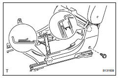
- Remove rear no. 1 Seatback assembly lh

- W/o rear no. 2 Seat: detach the 2 clamps and disconnect the cable from the reclining adjuster.
- Remove the 5 bolts and seatback.
- Remove rear seat lap type belt assembly center lh (see page sb-39)

- Remove rear seatback protector

- Using a clip remover, detach the 2 clips and open the fastening tape.
Notice:
If clips are damaged during removal, replace them.

- Detach the clip.
- Remove the 2 nuts and protector.
- Remove rear no. 1 Seatback cover

- Lift up the seatback cover and remove the 13 hog rings.

- Detach the 4 claws and remove the 2 headrest supports.
- Remove the seatback cover (with pad) from the seatback frame.

- Remove the 3 hog rings and seatback cover from the seatback pad.
- Remove rear seat cover lh

- Remove the 2 screws.
- Using a screwdriver, detach the 2 claws and remove the cover.
Hint:
Tape the screwdriver tip before use.
- Remove rear seatback cover lh

- Remove the 2 screws.
- Using a screwdriver, detach the 2 claws and remove the cover.
Hint:
Tape the screwdriver tip before use.
 Removal
Remove package tray trim pocket subassembly
(w/o rear no. 2 Seat)
Remove tonneau cover assembly (w/o rear
no. 2 Seat)
Remove rear floor no. 1 Board (w/o rear no.
2 Seat)
Remove deck b ...
 Reassembly
Caution:
Wear protective gloves. Sharp areas on the seatback
frame, seat cushion frame and reclining adjuster may
injure your hands.
Hint:
A bolt without a torque specification is shown in the st ...
Other materials:
Stop light switch circuit
Description
When the stop light switch is turned on, current flows to the stop lights to
illuminate them.
Wiring diagram
Inspection procedure
Inspect fuse (stop)
Remove the stop fuse from the instrument panel
junction block.
Measure the resistance of the fuse.
Standard resi ...
Blower motor circuit
Description
When the heater control (blower switch) is set to position 1 or higher, the
contact of the htr relay is
closed, current flows to the blower motor, and the blower motor operates. The
blower motor speed can be
changed by exchanging the ground and the blower resistor circuit with the ...
Outside rear view mirrors
The rear view mirror's position
can be adjusted to
enable sufficient confirmation
of the rear view.
â– When using the outside rear
view mirrors in a cold weather
When it is cold and the outside rear
view mirrors are frozen, it may not
be possible to fold/extend them or
adjust the mirror surface. Rem ...
