
Toyota RAV4 (XA40) 2013-2018 Service Manual: Diagnosis system
- Description
- Sliding roof system data and diagnostic trouble codes (dtcs) can be read through the vehicle's data link connector 3 (dlc3). When the system seems to be malfunctioning, use the intelligent tester to check for malfunctions and perform repairs.
- Check dlc3
The vehicle uses the iso 15765-4 for communication protocol. The terminal arrangement of the dlc3 complies with iso 15031-03 and matches the iso 15765-4 format.
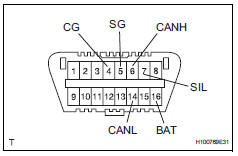
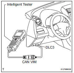
Hint:
Connect the cable of the intelligent tester to the dlc3, turn the ignition switch on and attempt to use the tester.
If the display indicates that a communication error has occurred, there is a problem either with the vehicle or with the tester.
- If communication is normal when the tester is connected to another vehicle, inspect the dlc3 of the original vehicle.
- If communication is still not possible when the tester is connected to another vehicle, the problem may be in the tester itself. Consult the service department listed in the tester's instruction manual.
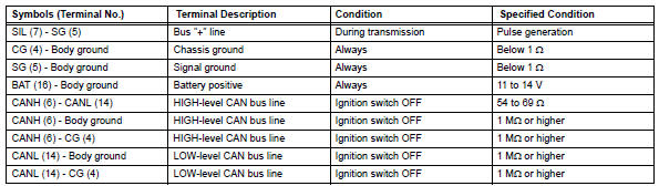
If the result is not as specified, the dlc3 may have a malfunction. Repair or replace the harness and connector.
 Terminals of ecu
Check sliding roof drive gear subassembly (sliding roof ecu)
Disconnect the p6 ecu connector.
Measure the resistance and voltage of the wire
harness side connector.
Reconnec ...
 Dtc check / clear
Check dtc
Connect the intelligent tester to the dlc3.
Turn the ignition switch on and turn the tester on.
Select the following menu item: body / sliding roof /
dtc.
Check the dtc( ...
Other materials:
How to proceed with troubleshooting
Hint:
Use these procedures to troubleshoot the cruise control
system.
*: Use the intelligent tester.
Vehicle brought to workshop
Inspect battery voltage
Standard voltage:
11 to 14 v
If the voltage is below 11 v, recharge or replace the battery
before proceeding.
Che ...
Precaution
If any of following conditions are met,
keep engine idling with a/c on (engine
speed at less than 2000 rpm) for at least 1
minute:
Refrigerant gas has been refilled or a/c parts have
been replaced.
A long time has elapsed since the engine was
stopped.
Notice:
If the engine s ...
Vehicle speed sensor "A"
description
The speed sensor detects the wheel speed and sends the appropriate signals to
the skid control ecu.
The skid control ecu converts these wheel speed signals into a 4-pulse signal
and outputs it to the ecm
via the combination meter. The ecm determines the vehicle speed based o ...
