Toyota RAV4 (XA40) 2013-2018 Service Manual: Open in stop light switch circuit
Description
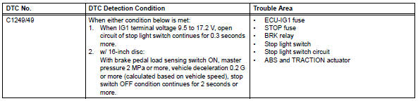
The skid control ecu detects the brake operating conditions through a signal transmitted by the stop light switch. The skid control ecu incorporates an open circuit detection circuit. This dtc is set under either of the following conditions:
- An open is detected in the stop light signal input line when the stop light switch is off.
- An open is detected in the stop light circuit lead to the ground when the stop light switch is off.
Wiring diagram
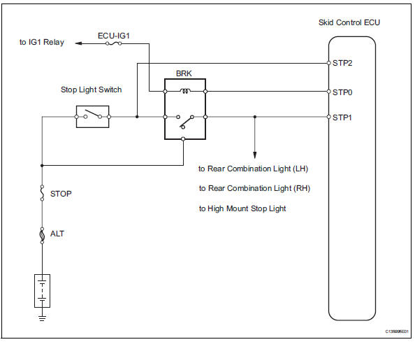
Inspection procedure
- Read value of intelligent tester (stop light switch)
- Check the data list for proper functioning of the stop light switch.
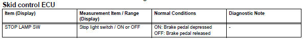
Ok: on (brake pedal is depressed) appears on the screen.


- Check wire harness (stp voltage)
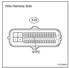
- Disconnect the a19 ecu connector.
- Measure the voltage of the wire harness side connector.
Standard voltage 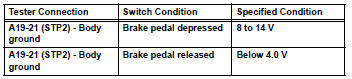


Replace abs and traction actuator assembly
- Inspect fuse (stop, ecu-ig1)
- Remove the stop fuse and ecu-ig1 fuse from the instrument panel junction block.
- Measure the resistance of the fuse.
Standard resistance:
below 1 


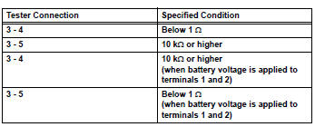
- Inspect stop light control relay (marking: brk)
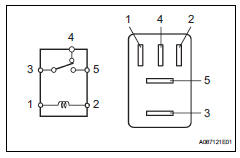
- Remove the stop light control relay from the engine room no. 1 Relay block.
- Measure the resistance of the relay.


- Inspect stop light switch assembly
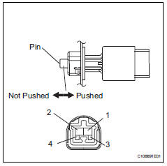
- Disconnect the stop light switch connector.
- Measure the resistance of the switch.
Standard resistance 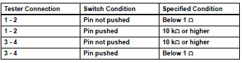


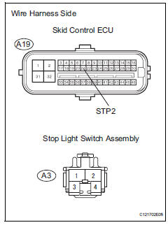
- Check wire harness (skid control ecu - stop light switch)
- Disconnect the a19 ecu connector.
- Disconnect the a3 switch connector.
- Measure the resistance of the wire harness side connectors.
- Disconnect the a19 ecu connector.
- Disconnect the a3 switch connector.
- Measure the resistance of the wire harness side connectors.
Standard resistance 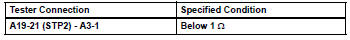

- Reconfirm dtc
- Clear the dtc (see page bc-47).
- Check if the same dtc is output (see page bc-47).
Result 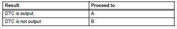


Replace abs and traction actuator assembly
 Master cylinder pressure sensor malfunction
Description
The master cylinder pressure sensor is connected to the skid control ecu in
the abs and traction
actuator.
Dtc c1281/81 can be detected when the master cylinder pressure sensor ...
 Open in pump motor circuit
Description
The motor relay drives the pump motor based on a signal from the skid control
ecu.
Wiring diagram
Refer to dtc c0273/13, c0274/14, c1361/91 (see page bc-79).
Inspection proce ...
Other materials:
Replacement
Replace generator drive end frame bearing
Remove the 4 screws and bearing retainer.
Using sst and a hammer, tap out the bearing.
Sst 09950-60010 (09951-00250), 09950-70010
(09951-07100)
Using sst and a press, press in a new bearing.
Sst 09950-60010 (09951-00250), 09 ...
Air conditioning control assembly (for automatic air conditioning system)
Components
Removal
Disconnect cable from negative battery
terminal
Notice:
Wait at least 90 seconds after disconnecting the
cable from the negative (-) battery terminal to
prevent airbag and seat belt pretensioner activation.
Remove no. 2 Instrument cluster finish
panel center ...
Data list / active test
Read data list
Hint:
Using the intelligent tester's data list allows switch,
sensor, actuator and other item values to be read without
removing any parts. Reading the data list early in
troubleshooting in one way to save time.
Connect the intelligent tester (with can vim) to the
dlc3 ...
