Toyota RAV4 (XA40) 2013-2018 Service Manual: Cruise control switch circuit
Description
This circuit sends signals to the ecm depending on the cruise control switch condition. The battery supplies positive (+) battery voltage to the cruise control switch. Then terminal ccs of the ecm receives the voltage according to the switch condition.
Wiring diagram

Inspection procedure
- Read value of intelligent tester (cruise control main switch)
- Check the data list for proper functioning of the cruise control switch.


Ok: when cruise control switch operation is performed, the results will be same as above.

- Inspect cruise control switch

- Disconnect the cruise control switch connector.
- Measure the resistance of the switch.
Standard resistance 


- Inspect spiral cable sub-assembly

- Disconnect the cruise control switch connector.
- Disconnect the e7 cable connector.
- Measure the resistance of the spiral cable.
Standard resistance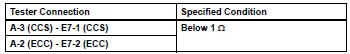


- Check wire harness (spiral cable - ecm and body ground)

- Disconnect the e7 cable connector.
- Disconnect the a9 ecm connector.
- Measure the resistance of the wire harness side connectors.
Standard resistance 


Proceed to next circuit inspection shown in problem symptoms table
 Communication
Description
The skid control ecu sends signals such as cruise control cancel demand
signals and brake operation
demand from ecm response signals to the ecm when the cruise control system is in ...
 Cruise control system cruise control main switch
Components
Removal
Caution:
Be sure to read the precautionary notices concerning the
srs airbag system before servicing it (see page rs-1).
Disconnect cable from negative battery
termi ...
Other materials:
Test mode procedure
Test mode check
Hint:
When entering the test mode, the tire pressure
warning ecu sets all the test dtcs first. After
completing the test mode for each inspection item, the
dtcs that are determined normal by the tire pressure
warning ecu will be erased.
The dtcs for other inspec ...
Srs warning light remains on
Description
The srs warning light is located on the combination meter.
When the srs is normal, the srs warning light comes on for approximately 6
seconds after the ignition
switch is turned from off to on, and then goes off automatically.
If there is a malfunction in the srs, the srs warni ...
Terminals of ecu
Skid control ecu
Hint:
*1: W/ 16-inch disc
*2: W/ downhill assist control
*3: For 2wd (w/ auto lsd)
Check skid control ecu
Disconnect the a19 ecu connector.
Measure the voltage and resistance of the wire
harness side connector.
Hint:
The voltage cannot be measured ...
