Toyota RAV4 (XA40) 2013-2018 Service Manual: Srs warning light remains on
Description
The srs warning light is located on the combination meter.
When the srs is normal, the srs warning light comes on for approximately 6 seconds after the ignition switch is turned from off to on, and then goes off automatically.
If there is a malfunction in the srs, the srs warning light comes on to inform the driver of a problem.
When terminals tc and cg of the dlc3 are connected, the dtc is displayed by blinking the srs warning light.
The srs is equipped with a voltage-increase circuit (dc-dc converter) in the center airbag sensor in case the source voltage drops.
When the battery voltage drops, the voltage-increase circuit (dc-dc converter) functions to increase the voltage of the srs to normal voltage.
A malfunction in this circuit is not recorded in the center airbag sensor . The srs warning light automatically goes off when the source voltage returns to normal.
The signal to illuminate the srs warning light is transmitted from the center airbag sensor to the combination meter through the multiplex communication system.
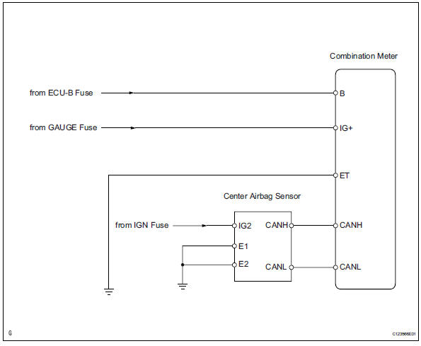
Wiring diagram
Inspection procedure
Check battery
- Measure the voltage of the battery.
Standard voltage: 11 to 14 v

- Check connector
- Turn the ignition switch off.
- Disconnect the negative (-) terminal cable from the battery, and wait for at least 90 seconds.
- Check that the connectors are properly connected to the center airbag sensor and combination meter.
Ok: the connectors are properly connected.

- Check wire harness (source voltage of center airbag sensor assembly)
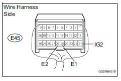
- Disconnect the e45 connector from the center airbag sensor .
- Connect the negative (-) terminal cable to the battery, and wait for at least 2 seconds.
- Turn the ignition switch on.
- Operate all components of the electrical system (defogger, wipers, headlight, heater blower, etc.).
- Measure the voltage of the wire harness side connectors.
Standard voltage 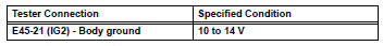
- Turn the ignition switch off.
- Measure the resistance of the wire harness side connectors.
Standard resistance 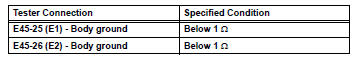

- Check wire harness (source voltage of combination meter)
- Disconnect the negative (-) terminal cable from the battery, and wait for at least 90 seconds.
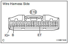
- Disconnect the e19 connector from the combination meter.
- Connect the negative (-) terminal cable to the battery, and wait for at least 2 seconds.
- Turn the ignition switch on.
- Measure the voltage of the wire harness side connectors.
Standard voltage 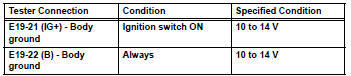
- Turn the ignition switch off.
- Measure the resistance of the wire harness side connectors.
Standard resistance 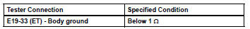

- Check srs warning light
- Turn the ignition switch off.
- Disconnect the negative (-) terminal cable from the battery, and wait for at least 90 seconds.
- Connect the e19 connector to the combination meter.
- Connect the negative (-) terminal cable to the battery, and wait for at least 2 seconds.
- Turn the ignition switch on.
- Check the srs warning light condition.
Ok: after the primary check period, srs warning light goes off for approximately 10 seconds, and turning it on is continued.
Hint:
The primary check period shows approximately 6 seconds after the ignition switch is on.

Replace center airbag sensor assembly
 Source voltage drop
Description
The srs is equipped with a voltage-increase circuit (dc-dc converter) in the
center airbag sensor in
case the source voltage drops.
When the source voltage drops, the voltage-increa ...
 Srs warning light does not come on
Description
The srs warning light is located on the combination meter.
When the srs is normal, the srs warning light comes on for approximately 6
seconds after the ignition
switch is turned fro ...
Other materials:
Compressor solenoid circuit (2005/11-2006/01)
Description
In this circuit, the compressor receives a refrigerant compression demand
signal from the air conditioning
amplifier. Based on this signal, the compressor changes the degree of
refrigerant compression.
Wiring diagram
Inspection procedure
Read value of intelligent ...
Air mix damper control servo motor circuit (passenger side)
Description
The air mix damper servo sends pulse signals to indicate the damper position
to the air conditioning
amplifier. The air conditioning amplifier activates the motor (normal or
reverse) based on these signals to
move the air mix damper (passenger seat) to the appropriate position ...
On-vehicle inspection
Check fan and generator v belt
Visually check the drive belt for excessive wear,
frayed cords, etc.
If any defect has been found, replace the drive belt.
Hint:
Cracks on the rib side of a drive belt are considered
acceptable.
If the drive belt has chunks missing from the r ...
