Toyota RAV4 (XA40) 2013-2018 Service Manual: Vehicle speed sensor "A"
![]()
description
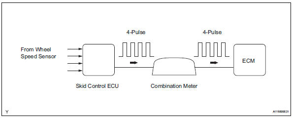
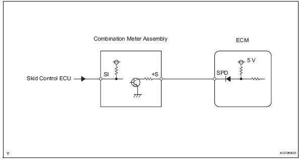
The speed sensor detects the wheel speed and sends the appropriate signals to the skid control ecu.
The skid control ecu converts these wheel speed signals into a 4-pulse signal and outputs it to the ecm via the combination meter. The ecm determines the vehicle speed based on the frequency of these pulse signals.
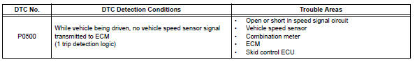
Monitor description
The ecm assumes that the vehicle is being driven, when the indicated engine speed is more than 2,300 rpm and 30 seconds have elapsed since the park/neutral position (pnp) switch was turned off. If there is no speed signal from the combination meter, despite these conditions being met, the ecm interprets this as a malfunction in the speed signal circuit. The ecm then illuminates the mil and sets the dtc.
Monitor strategy
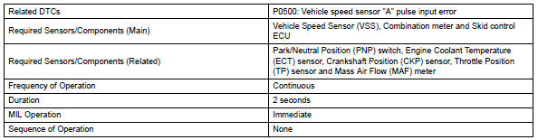
Typical enabling conditions
![]()
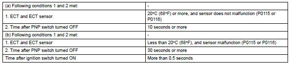
Typical malfunction thresholds
![]()
Wiring diagram
Inspection procedure
Hint:
Read freeze frame data using the intelligent tester. Freeze frame data records the engine condition when malfunctions are detected. When troubleshooting, freeze frame data can help determine if the vehicle was moving or stationary, if the engine was warmed up or not, if the air-fuel ratio was lean or rich, and other data from the time the malfunction occurred.
- Check operation of speedometer
- Drive the vehicle and check whether the operation of the speedometer in the combination meter is normal.
Hint:
- The vehicle speed sensor is operating normally if the speedometer reading is normal.
- If the speedometer does not operate, check it by following the procedure described in speedometer malfunction (see page me-41).


- Read value using intelligent tester (vehicle spd)
- Connect the intelligent tester to the dlc3.
- Turn the ignition switch on.
- Turn the tester on.
- Select the following menu items: diagnosis / enhanced obd ii / data list / primary / vehicle spd.
- Drive the vehicle.
- Read the value displayed on the tester.
Ok: vehicle speeds displayed on tester and speedometer display are equal.


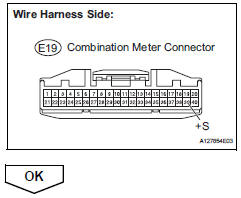
- Check combination meter assembly (+s voltage)
- Disconnect the e19 combination meter connector.
- Turn the ignition switch on.
- Measure the voltage between the terminal of the combination meter and the body ground.
Standard voltage 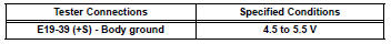
- Reconnect the combination meter connector.
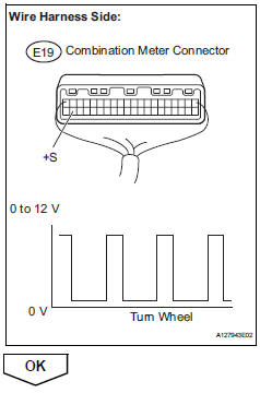
- Check combination meter assembly (spd signal waveform)
- Shift the transmission gear selector lever to the neutral position.
- Jack up the vehicle.
- Turn the ignition switch on.
- Check the voltage between the terminal of the combination meter and the body ground while the wheel is turned slowly.
Standard voltage 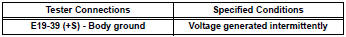
Hint:
The output voltage should fluctuate up and down, similarly to the diagram, when the wheel is turned slowly.
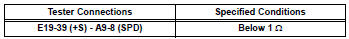
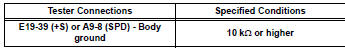
- Check harness and connector (combination meter assembly - ecm)
- Disconnect the e19 combination meter connector.
- Disconnect the a9 ecm connector.
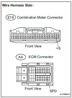
- Check the resistance.
Standard resistance (check for open)
Standard resistance (check for short)
- Reconnect the combination meter connector.
- Reconnect the ecm connector.
 Evaporative emission control system leak detected
Dtc summary
Description
The description can be found in the evap (evaporative emission) system (see
page es-335).
Inspection procedure
Refer to the evap system (see page es-340).
Monito ...
 Brake switch "A" / "B" correlation
Description
The stop light switch is a duplex system that transmits two signals: stp and
st1-. These two signals are
used by the ecm to monitor whether or not the brake system is working prope ...
Other materials:
Footwell light
On-vehicle inspection
Inspect footwell light
Connect the battery's positive (+) lead to terminal 2
and the negative (-) lead to terminal 1, then check
that the light comes on.
Ok:
light comes on.
If the result is not as specified, replace the light. ...
How to proceed with troubleshooting
Hint:
Use these procedures to troubleshoot the vehicle stability
control system.
*: Use the intelligent tester.
Vehicle brought to workshop
Inspect battery voltage
Standard voltage:
11 to 14 v
If the voltage is below 11 v, recharge or replace the battery
before proceedin ...
Solar sensor circuit (driver side)
Description
The solar sensor, which is installed on the upper side of the instrument
panel, detects sunlight and
controls the air conditioning auto mode. The output voltage from the solar
sensor varies in accordance
with the amount of sunlight. When the sunlight increases, the output volt ...
