Toyota RAV4 (XA40) 2013-2018 Service Manual: Evaporative emission control system leak detected
Dtc summary
Description
The description can be found in the evap (evaporative emission) system (see page es-335).
Inspection procedure
Refer to the evap system (see page es-340).
Monitor description
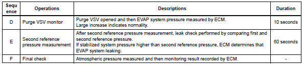
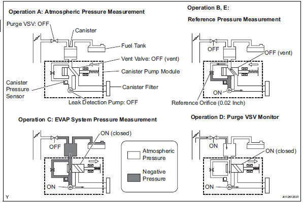
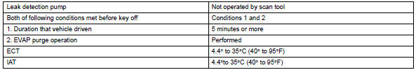
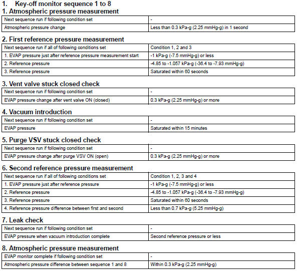
5 Hours* after the ignition switch is turned off, the leak detection pump creates negative pressure (vacuum) in the evap system. The ecm monitors for leaks and actuator malfunctions based on the evap pressure.
Hint:
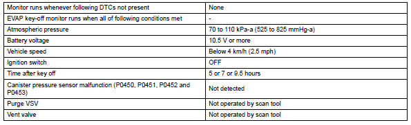
*: If the engine coolant temperature is not below 35°c (95°f) 5 hours after the ignition switch is turned off, the monitor check starts 2 hours later. If it is still not below 35°c (95°f) 7 hours after the ignition switch is turned off, the monitor check starts 2.5 Hours later.
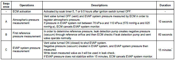
*: If only a small amount of fuel is in the fuel tank, it takes longer for the evap pressure to stabilize.
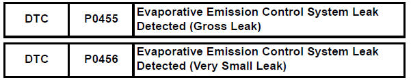
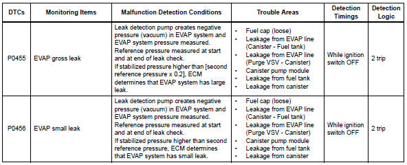
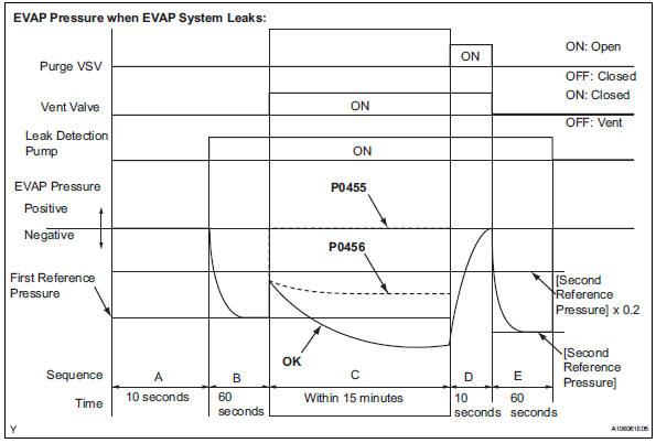
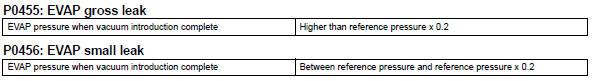
- P0455: evap gross leak
In operation c, the leak detection pump creates negative pressure (vacuum) in the evap system and the evap system pressure is measured. If the stabilized system pressure is higher than [second reference pressure x 0.2] (Near atmospheric pressure), the ecm determines that the evap system has a large leakage, illuminates the mil and sets the dtc (2 trip detection logic).
- P0456: evap very small leak
In operation c, the leak detection pump creates negative pressure (vacuum) in the evap system and the evap system pressure is measured. If the stabilized system pressure is higher than the second reference pressure, the ecm determines that the evap system has a small leakage, illuminates the mil and sets the dtc (2 trip detection logic).
Monitor strategy
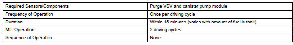
Typical enabling conditions
Typical malfunction thresholds
Monitor result
Refer to checking monitor status (see page es-17).
 Evaporative emission control system pressure sensor
Dtc summary
Hint:
The canister pressure sensor is built into the canister pump module.
Description
The description can be found in the evap (evaporative emission) system (see
page es ...
 Vehicle speed sensor "A"
description
The speed sensor detects the wheel speed and sends the appropriate signals to
the skid control ecu.
The skid control ecu converts these wheel speed signals into a 4-pulse signal ...
Other materials:
Passenger airbag on / off indicator circuit malfunction
Description
The passenger airbag on / off indicator circuit consists of the center airbag
sensor and the heater
control panel*1 or *2.
This circuit indicates the operation condition of the front passenger airbag,
the front passenger side airbag
and passenger side seat belt pretensioner ...
Utility vehicle
precautions
This vehicle belongs to the utility vehicle class, which has
higher ground clearance and narrower tread in relation to the
height of its center of gravity to make it capable of performing in
a wide variety of off-road applications.
Utility vehicle feature
Specific design characteristics give ...
Location of the interior lights
Rear interior light
Front interior lights/personal lights
Open tray lights (if equipped)*
Footwell lights (if equipped)*
Front cup holder lights (if equipped)*
*: These lights turn on when a door is unlocked.
When the shift lever is in a position other than P, the brightness of these
ligh ...
