Toyota RAV4 (XA40) 2013-2018 Service Manual: Evaporative emission system reference orifice
Dtc summary
Hint:
The reference orifice is located inside the canister pump module.
Description
The description can be found in the evap (evaporative emission) system (see page es-335).
Inspection procedure
Refer to the evap system (see page es-340).
Monitor description
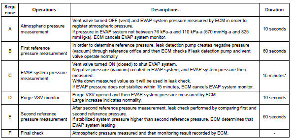
5 Hours* after the ignition switch is turned off, the leak detection pump creates negative pressure (vacuum) in the evap system. The ecm monitors for leaks and actuator malfunctions based on the evap pressure.
Hint:
*: If the engine coolant temperature is not below 35°c (95°f) 5 hours after the ignition switch is turned off, the monitor check starts 2 hours later. If it is still not below 35°c (95°f) 7 hours after the ignition switch is turned off, the monitor check starts 2.5 Hours later.

*: If only a small amount of fuel is in the fuel tank, it takes longer for the evap pressure to stabilize.
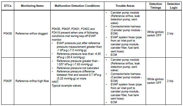
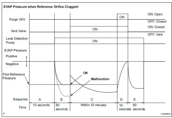
- P043e: reference orifice clogged
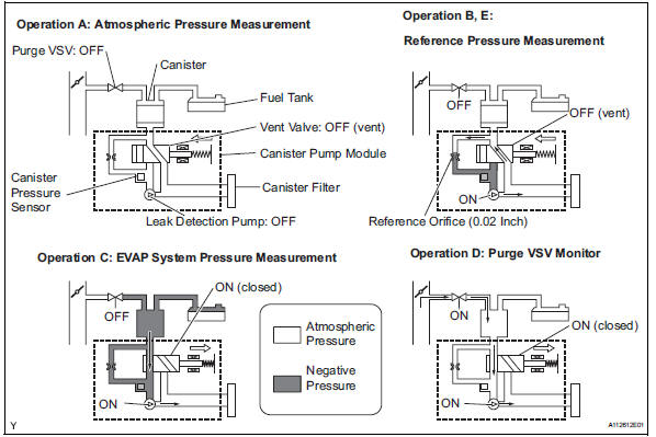
In operation b, the leak detection pump creates negative pressure (vacuum) through the reference orifice.
The evap system pressure is then measured by the ecm, using the canister pressure sensor, to determine the reference pressure. If the pressure is lower than -4.85 Kpa-g (-36.4 Mmhg-g), the ecm interprets this as a clog malfunction in the reference orifice, and stops the evap system monitor.
The ecm then illuminates the mil and sets the dtc (2 trip detection logic).
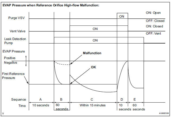
- P043f: reference orifice high-flow
In operation b, the leak detection pump creates negative pressure (vacuum) through the reference orifice.
The evap system pressure is then measured by the ecm using the canister pressure sensor to determine the reference pressure. If the pressure is higher than -1.057 Kpa-g (-7.93 Mmhg-g), the ecm interprets this as a high-flow malfunction in the reference orifice, and stops the evap system monitor. The ecm then illuminates the mil and sets the dtc (2 trip detection logic).
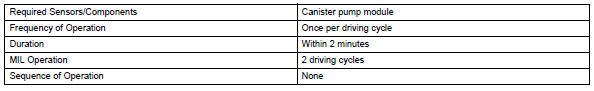
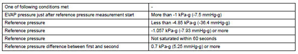
Monitor strategy
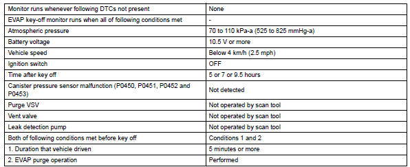
Typical enabling conditions
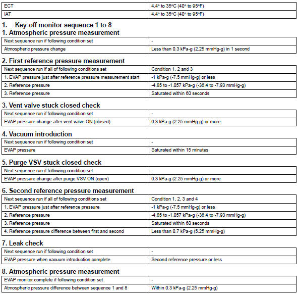
Typical malfunction thresholds
"Saturated" indicates that the evap pressure change is less than 0.286 Kpa-g (2.14 Mmhg-g) in 60 seconds.
Monitor result
Refer to checking monitor status (see page es-17).
 Catalyst system efficiency below threshold (bank 1)
Monitor description
The ecm uses sensors mounted in front of and behind the three-way catalytic
converter (twc) to
monitor its efficiency.
The first sensor, the air-fuel ratio (a/f) sensor, ...
 Evaporative emission control system incorrect purge flow
Dtc summary
Description
The description can be found in the evap (evaporative emission) system (see
page es-335).
Inspection procedure
Refer to the evap system (see page es-340).
Monito ...
Other materials:
Occupant classification system malfunction
Description
The occupant classification system circuit consists of the center airbag
sensor and the occupant
classification system.
When the center airbag sensor receives signals from the occupant classification
ecu, it determines
whether or not the front passenger airbag, front seat side ...
Open in abs solenoid relay circuit
Description
The solenoid relay supplies power to the abs solenoid and trc solenoid.
After the ignition switch is turned on, the vehicle speed has reached 6 km/h (4
mph) and the solenoid is
determined to be normal by the initial check self-diagnosis, the relay switches
on. If any open or ...
Ecu malfunction
Description
Inspection procedure
If the power steering ecu detects these dtcs, it will shut off the motor
relay circuit (built into the power
steering ecu) and stop power assist. However, power assist continues if dtc
c1533 is output.
Reconfirm dtc
Check for dtc.
Ok:
dtc i ...
