Toyota RAV4 (XA40) 2013-2018 Service Manual: Occupant classification system malfunction
Description
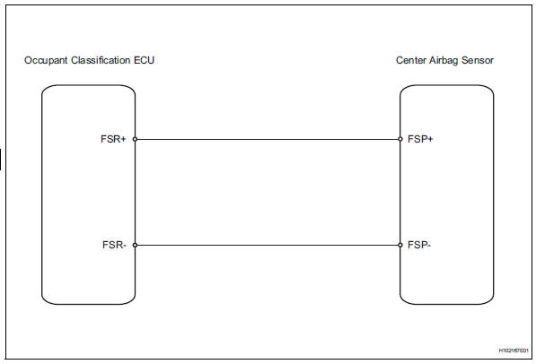
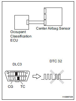
The occupant classification system circuit consists of the center airbag sensor and the occupant classification system.
When the center airbag sensor receives signals from the occupant classification ecu, it determines whether or not the front passenger airbag, front seat side airbag rh and seat belt pretensioner rh should be operated.
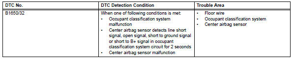
Dtc b1650/32 is set when a malfunction is detected in the occupant classification system circuit.
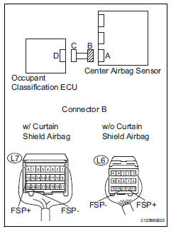
Wiring diagram
Inspection procedure
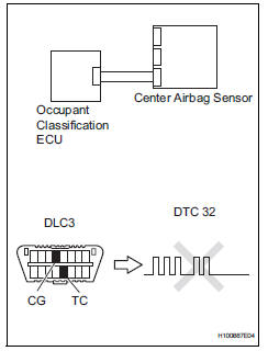
- Check for dtc (center airbag sensor)
- Turn the ignition switch on, and wait for at least 60 seconds.
- Clear the dtcs (see page rs-49).
- Turn the ignition switch off.
- Turn the ignition switch on, and wait for at least 60 seconds.
- Check for dtcs (see page rs-49).
Ok: dtc b1650/32 is not output.
Hint:
Dtcs other than b1650/32 may be output at this time, but they are not related to this check.

- Check for dtc (occupant classification ecu)
- Turn the ignition switch on, and wait for at least 10 seconds.
- Using the intelligent tester (with can vim), check for dtcs of the occupant classification ecu (see page rs- 249).
Ok: dtc is not output.

- Check connection of connector
- Turn the ignition switch off.
- Disconnect the cable from the negative (-) battery terminal, and wait for at least 90 seconds.
- Check that the connectors are properly connected to the center airbag sensor and the occupant classification ecu.
Ok: the connectors are properly connected.

- Check floor wire (open)
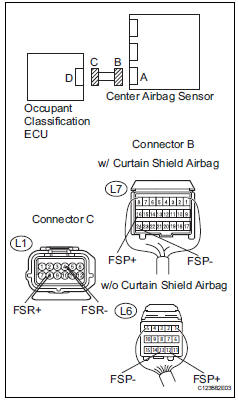
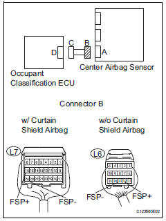
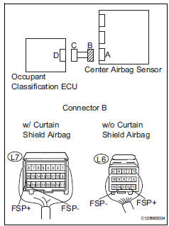
- Disconnect the connectors from the center airbag sensor and occupant classification ecu.
- Using a service wire, connect l1-8 (fsr+) and l1-4 (fsr-) of connector c.
Notice:
Do not forcibly insert the service wire into the terminals of the connector when connecting.
- Measure the resistance of the wire harness side connector.
Standard resistance:
W/ curtain shield airbag 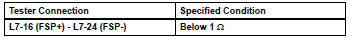
W/o curtain shield airbag 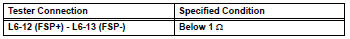

- Check floor wire (short)
- Disconnect the service wire from connector c.
- Measure the resistance of the wire harness side connector.
Standard resistance:
W/ curtain shield airbag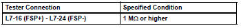
W/o curtain shield airbag 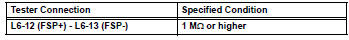

- Check floor wire (to b+)
- Connect the cable to the negative (-) battery terminal, and wait for at least 2 seconds.
- Turn the ignition switch on.
- Measure the voltage of the wire harness side connector.
Standard voltage:
W/ curtain shield airbag 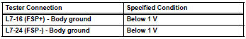
W/o curtain shield airbag 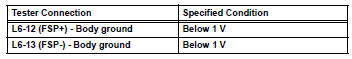


- Check floor wire (to ground)
- Turn the ignition switch off.
- Disconnect the cable from the negative (-) battery terminal, and wait for at least 90 seconds.
- Measure the resistance of the wire harness side connector.
Standard resistance:
W/ curtain shield airbag 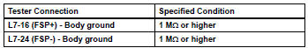
W/o curtain shield airbag 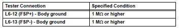

- Check center airbag sensor assembly
- Replace the center airbag sensor (see page rs-374).
Hint:
Perform the inspection using parts from a normal vehicle when possible.
- Connect the connectors to the center airbag sensor.
- Connect the cable to the negative (-) battery terminal, and wait for at least 2 seconds.
- Turn the ignition switch on, and wait for at least 60 seconds.
- Clear the dtcs (see page rs-49).
- Turn the ignition switch off
- Turn the ignition switch on, and wait for at least 60 seconds.
- Check for dtcs (see page rs-49).
Ok: dtc b1650/32 is not output.
Hint:
Dtcs other than b1650/32 may be output at this time, but they are not related to this check.

- Replace occupant classification ecu
- Turn the ignition switch off.
- Disconnect the cable from the negative (-) battery terminal, and wait for at least 90 seconds
- Replace the occupant classification ecu (see page rs- 392).

- Perform zero point calibration
- Connect the cable to the negative (-) battery terminal, and wait for at least 2 seconds.
- Turn the ignition switch on.
- Using the intelligent tester, perform the zero point calibration (see page rs-241).
Ok: completed is displayed on the tester.

- Perform sensitivity check
- Using the intelligent tester, perform the sensitivity check (see page rs-241).
Standard value: 27 to 33 kg (59.52 To 72.75 Lb)

End
 Front passenger side satellite sensor bus initialization incomplete
Description
When the center airbag sensor receives signals from the lateral deceleration
sensor, it determines
whether or not the srs should be activated.
Dtc b1648/82 is recorded when a ma ...
 Seat position airbag sensor circuit malfunction
Description
The seat position sensor circuit consists of the center airbag sensor and the
seat position sensor.
Dtc b1653/35 is recorded when a malfunction is detected in the seat position
...
Other materials:
Reassembly
Bearing position
Standard bearing position
Install differential gear lube apply tube
Install the apply tube and clamp to the transaxle
housing with the bolt.
Torque: 9.8 N*m (100 kgf*cm, 87 in.*Lbf)
Notice:
Make sure to insert the pipe to the stopper.
Instal ...
Multiplex communication circuit
Description
The air conditioning amplifier communicates data with the ecm and combination
meter through the can
communication system.
Wiring diagram
Inspection procedure
Check dtc
Clear the dtc (see page ac-127).
Read the dtc (see page ac-127).
Result
Go to can ...
Registration
In case of tire pressure warning ecu
replacement
Read id stored in the old ecu using the intelligent
tester.
In case of tire pressure warning valve and
transmitter and/or tire pressure warning
ecu replacement
Read the id written on the tire pressure monitor
valve.
...
