Toyota RAV4 (XA40) 2013-2018 Service Manual: Test mode procedure
Hint:
- By switching the skid control ecu from normal mode to test mode, abnormality detection sensitivity is enhanced and troubleshooting can be conducted efficiently.
- Perform a sensor check in test mode after the speed sensor or sensor rotor has been repaired or replaced.
- If the ignition switch is turned from on to acc or off during test mode, dtcs related to the signal check function will be erased.
- During test mode, the skid control ecu stores all dtcs related to the signal check function, and the dtcs are erased if normality is confirmed. Any remaining dtcs are those indicating abnormalities that were found.
- Check sensor signal by test mode (when using intelligent tester)
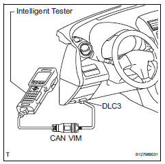
- Procedures for test mode:
- Turn the ignition switch off.
- Check that the steering wheel is in the centered position.
- Check that the shift lever is in the p position and apply the parking brake.
- Connect the intelligent tester (with can vim) to the dlc3.
- Turn the ignition switch on.
- Turn the tester on.
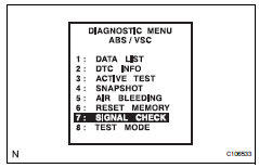
- Set the intelligent tester to test mode (select "signal check").
Hint:
Refer to the intelligent tester operator's manual for further details.
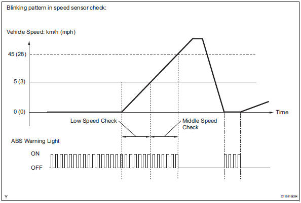
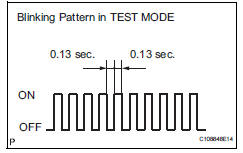
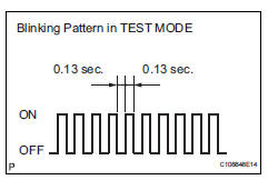
- Check that the abs warning light and vsc warning light blink as shown in the illustration.
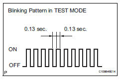
Hint:
If the abs warning light and vsc warning
warning light do not blink, check the ts and cg
terminal circuit, and abs and vsc warning light
circuits. 
- Start the engine.
- W/ 16-inch disc only: check the lost booster pressure judgment and perform the master cylinder pressure sensor zero point calibration.
Notice:
Preform the check in the lost booster pressure state (negative pressure in the booster is depressurized).
- Turn the ignition switch on.
- Check that the brake warning light comes on when depressing the brake pedal with a force of 59 n (6 kgf, 13.2 Lbf) or more for 1 second or more. (The lost booster pressure state is judged normal.)
- Start the engine depressing the brake pedal with a force of 59 n (6 kgf, 13.2 Lbf) or more for 1 second or more.
- Check that the brake warning light goes off when quickly releasing the brake pedal. (The lost booster pressure state is judged normal.)
- Leave the vehicle for 1 second or more. (Master cylinder pressure sensor zero point calibration.)
Notice:
- If you slowly depress the brake pedal or depress it again, master cylinder pressure sensor zero point calibration is not performed normally.
- If the lost booster pressure judgment check is not completed normally, the master cylinder pressure sensor check is not judged.
- If a recheck is performed after the engine has started, end the test mode, enter test mode again, and release the vacuum in the booster by pumping the brake pedal prior to the recheck.
- Check the deceleration sensor.
- Keep the vehicle stationary on a level surface for 1 second or more.
Hint:
The deceleration sensor check can be performed together with the following master cylinder pressure sensor check.
- Check the master cylinder pressure sensor.
- Leave the vehicle in a stationary condition and
release the brake pedal for 1 second or more,
and quickly depress the brake pedal with a force
of 98 n (10 kgf, 22 lbf) or more for 1 second.
Check that the abs warning light remains illuminated for 3 seconds.
Hint:
- Ensure that the abs warning light comes on.
- While the abs warning light remains illuminated, continue depressing the brake pedal with a force of 98 n (10 kgf, 22 lbf) or more.
- The abs warning light comes on for 3 seconds every time the brake pedal operation above is performed.
- Check the speed sensor.
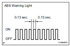
- Drive the vehicle straight forward at a speed of 45 km/h (28 mph) or more for several seconds.
- Check that the abs warning light goes off.
Notice:
- The speed sensor check may not be completed if the sensor check is started with the steering wheel turned or one or more wheels spinning.
- If the speed sensor check is commenced while the steering wheel is turned, the abs warning light may come on after the low speed check is finished.
- The abs warning light comes on immediately when an abnormality is detected.
- When the speed sensor signal is normal, the abs warning light goes off while driving at 45 km/h (28 mph) or more, and blinks in the test mode pattern while the vehicle is stationary.
- Do not drive the vehicle at a speed of 80 km/h (50 mph) or more after the abs warning light turns off, because test mode dtcs are set again when the vehicle speed exceeds 80 km/h (50 mph).
- Stop the vehicle.
- Check the yaw rate sensor.
- Move the shift lever to p and set the parking brake lever.
- Check that the vsc warning light is blinking as shown in the illustration.
- Keep the vehicle stationary on a level surface for 1 second or more.
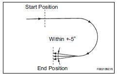
- Shift the shift lever to the d position and drive the vehicle at a speed of approximately 5 km/h (3 mph), and turn the steering wheel either to the left or right 90° or more to turn the vehicle through 180°.
- Stop the vehicle, move the shift lever into the p position, and then apply the parking brake.
- Check that the skid control buzzer sounds for 3 seconds.
Hint:
- If the skid control buzzer sounds, the signal check has been completed normally.
- If the skid control buzzer does not sound, check the skid control buzzer circuit (see page bc-172).
- If the skid control buzzer still does not sound, there is a malfunction in the yaw rate sensor, so check for dtcs
- Drive the vehicle in a 180° semi circle. At the end of the turn, the direction of the vehicle should be within 180 +-5° of its start position.
- Complete the vehicle turn within 20 seconds.
- Do not spin the wheels.
- W/ downhill assist control only:
Check the downhill assist control operation switch.
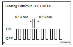
- Check that the vsc warning light is blinking as shown in the illustration.
- Check the downhill assist control switch.
1. Push the downhill assist control switch on.
2. Push the downhill assist control switch off.
- W/ auto lsd only:
- Check that the auto lsd light illuminates only when the auto lsd switch is pressed.
- Check the end of sensor.
- When the sensor check is successfully completed, the abs warning light blinks in the test mode pattern when the vehicle is stopped, and goes off when the vehicle is driven.
Notice:
If the sensor check is not completed, the abs warning light blinks even while the vehicle is driving and the abs does not operate.
- Read the dtcs of signal check function.
- Read the dtc(s) by following the instructions on the tester screen.
Notice:
- If only the dtcs are displayed, repair the malfunction area and clear the dtcs.
- If the dtcs or test mode codes (dtc of signal check function) are displayed, repair the malfunction area, clear the dtcs and perform the test mode inspection.
Hint:
See the list of the dtcs (refer to "dtc of test mode function (signal check)" below).
- Check sensor signal by test mode (when not using intelligent tester)
- Procedures for test mode:
- Turn the ignition switch off.
- Check that the steering wheel is in the centered position.
- Check that the shift lever is in the p position and apply the parking brake.
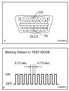
- Using sst, connect terminals 12 (ts) and 4 (cg) of the dlc3.
Sst 09843-18040
- Turn the ignition switch on.
- Check that the abs warning light and vsc warning light blink as shown in the illustration.
Hint:
If the abs warning light and vsc warning
warning light and multi information display and
master caution indicator light do not blink, check
the ts and cg terminal circuit, and abs and
vsc warning light circuits.

- Start the engine.
- W/ 16-inch disc:
Check the lost booster pressure judgment and perform the master cylinder pressure sensor zero point calibration.
Notice:
Preform the check in the lost booster pressure state (negative pressure in the booster is depressurized).
- Turn the ignition switch on.
- Check that the brake warning light comes on when depressing the brake pedal with a force of 59 n (6 kgf, 13.2 Lbf) or more for 1 second or more. (The lost booster pressure state is judged normal.)
- Start the engine depressing the brake pedal with a force of 59 n (6 kgf, 13.2 Lbf) or more for 1 second or more.
- Check that the brake warning light goes off when quickly releasing the brake pedal. (The lost booster pressure state is judged normal.)
- Leave the vehicle for 1 second or more. (Master cylinder pressure sensor zero point calibration.)
Notice:
- If you slowly depress the brake pedal or depress it again, master cylinder pressure sensor zero point calibration is not performed normally.
- If the lost booster pressure judgment check is not completed normally, the master cylinder pressure sensor check is not judged.
- If a recheck is performed after the engine has started, end the test mode, enter test mode again, and release the vacuum in the booster by pumping the brake pedal prior to the recheck
- Check the deceleration sensor.
- Keep the vehicle stationary on a level surface for 1 second or more.
Hint:
The deceleration sensor check can be performed together with the following master cylinder pressure sensor check.
- Check the master cylinder pressure sensor.
- Leave the vehicle in a stationary condition and
release the brake pedal for 1 second or more,
and quickly depress the brake pedal with a force
of 98 n (10 kgf, 22 lbf) or more for 1 second.
Check that the abs warning light remains illuminated for 3 seconds.
Hint:
- Ensure that the abs warning light comes on.
- While the abs warning light remains illuminated, continue depressing the brake pedal with a force of 98 n (10 kgf, 22 lbf) or more.
- The abs warning light comes on for 3 seconds every time the brake pedal operation above is performed.
- Check the speed sensor.
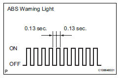
- Check that the abs warning light is blinking as shown in the illustration.
- Check the speed sensor signal.
1. Drive the vehicle straight forward at a speed of 45 km/h (28 mph) or more for several seconds.
2. Check that the abs warning light goes off.
Notice:
- The speed sensor check may not be completed if the sensor check is started with the steering wheel turned or one or more wheels spinning.
- If the speed sensor check is commenced while the steering wheel is turned, the abs warning light may come on after the low speed check is finished.
- The abs warning light comes on immediately when an abnormality is detected.
- When the speed sensor signal is normal, the abs warning light goes off while driving at 45 km/h (28 mph) or more, and blinks in the test mode pattern while the vehicle is stationary.
- Do not drive the vehicle at a speed of 80 km/h (50 mph) or more after the abs warning light turns off, because test mode dtcs are set again when the vehicle speed exceeds 80 km/h (50 mph).
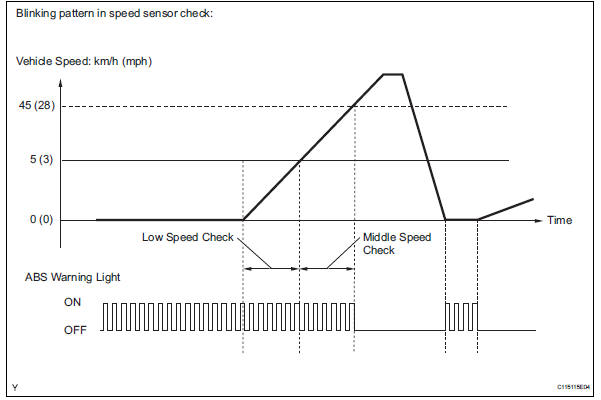
3. Stop the vehicle.
- Check the yaw rate sensor.
- Move the shift lever to p and set the parking brake lever.
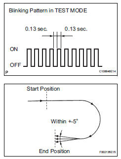
- Check that the vsc warning light is blinking as shown in the illustration.
- Keep the vehicle stationary on a level surface for 1 second or more.
- Shift the shift lever to the d position and drive the vehicle at a speed of approximately 5 km/h (3 mph), and turn the steering wheel either to the left or right 90° or more to turn the vehicle through 180°.
- Stop the vehicle, move the shift lever into the p position, and then apply the parking brake.
- Check that the skid control buzzer sounds for 3 seconds.
Hint:
- If the skid control buzzer sounds, the signal check has been completed normally.
- If the skid control buzzer does not sound, check the skid control buzzer circuit (see page bc-172).
- If the skid control buzzer still does not sound, there is a malfunction in the yaw rate sensor, so check for dtcs.
- Drive the vehicle in a 180° semi circle. At the end of the turn, the direction of the vehicle should be within 180 +-5° of its start position.
- Complete the vehicle turn within 20 seconds.
- Do not spin the wheels.
- W/ downhill assist control only:
Check the downhill assist control operation switch.
- Check that the vsc warning light is blinking as shown in the illustration.
- Check the downhill assist control switch.
1. Push the downhill assist control switch on.
2. Push the downhill assist control switch off.
- W/ auto lsd only:
Check the end of the sensor.
- When the sensor check is successfully completed, the abs warning light blinks in the test mode pattern when the vehicle is stopped, and goes off when the vehicle is driven.
Notice:
If the sensor check is not completed, the abs warning light blinks even while the vehicle is driving and the abs does not operate.
- Read the dtcs of the signal check function.
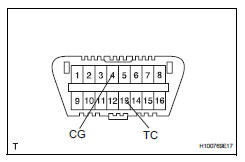
- Using sst, connect terminals 13 (tc) and 4
(cg) of the dlc3.
Sst 09843-18040
- Turn the ignition switch on.
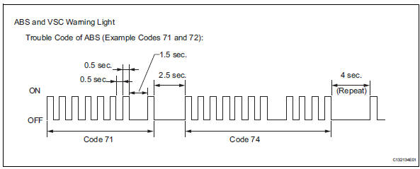
- Count the number of blinks of the abs and vsc warning light.
Hint:
As an example, the blinking patters of dtcs 71 and 74 are shown below.
Notice:
- If only dtcs are displayed, repair the malfunctioning area and clear the dtcs.
- If the dtcs or test mode codes (dtc of signal check function) are displayed, repair the malfunctioning area, clear the dtcs and perform the test mode inspection.)
Hint:
- If more than 1 malfunction is detected at the same time, the lowest numbered code will be displayed first.
- See the list of dtcs (refer to "dtc of test mode function (signal check)" below).
- If all sensors are normal, a normal system code is output (the light comes on for 0.25 Seconds at intervals of 0.25 Seconds).
- After the check, disconnect sst from terminals 13 (tc) and 4 (cg) of the dlc3.
- Turn the ignition switch off.
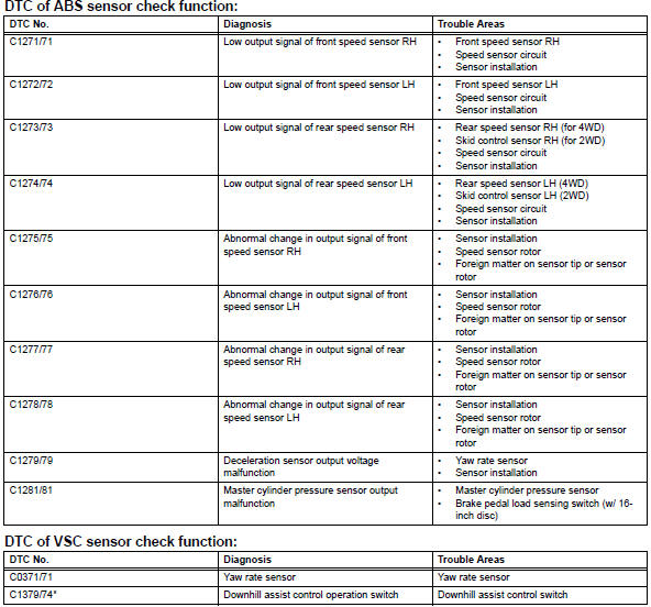
- Dtc of test mode function (signal check)
Hint:
- *: W/ downhill assist control
- The dtcs in this table are only output in test mode.
- The detection of dtcs from c1271/71 to c1274/74 is completed before the vehicle speed reaches 5 km/h (3 mph).
- The detection of dtcs from c1275/75 to c1278/78 is completed before the vehicle speed reaches 45 km/h (28 mph).
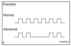
- C1271/71 to c1274/74: the speed output from only one wheel is extremely low despite other wheel speed outputs reaching 5 km/h (3 mph).
- C1275/75 to c1278/78: the abnormal speed sensor Output frequency is as shown in the illustration.
 Calibration
Description
After replacing components relating to the vsc or
performing "front wheel alignment adjustment",
clear and read the sensor calibration data.
Follow the chart to pe ...
 Problem symptoms table
Hint:
Use the table below to help determine the cause of the
problem symptom. The potential causes of the symptoms
are listed in order of probability in the "suspected area"
column ...
Other materials:
Cargo and luggage
Take notice of the following
information about storage
precautions, cargo capacity
and load.
WARNING
â– Things that must not be carried
in the luggage compartment
The following things may cause a
fire if loaded in the luggage compartment:
Receptacles containing gasoline
Aerosol cans
â– Storage p ...
Disposal
Hint:
When scrapping vehicles equipped with a seat belt
pretensioner or disposing of a front seat outer belt (with seat
belt pretensioner), always first activate the seat belt
pretensioner in accordance with the procedures described
below. If any abnormality occurs during activation of the seat ...
How to proceed with troubleshooting
Hint:
Use these procedures to troubleshoot the tire pressure
warning system.
*: Use the intelligent tester.
Vehicle brought to workshop
Inspect battery voltage
Standard voltage:
11 to 14 v
If the voltage is below 11 v, recharge or replace the battery
before proceeding.
...
