Toyota RAV4 (XA40) 2013-2018 Service Manual: Steering gear
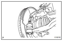
Components


Removal
- Position front wheels facing straight ahead
- Disconnect cable from negative battery terminal
Caution:
Wait at least 90 seconds after disconnecting the cable from the negative (-) battery terminal to prevent airbag and seat belt pretensioner activation.
- Remove front wheel
- Disconnect tie rod end sub-assembly lh

- Remove the cotter pin and castle nut.
- Using sst, disconnect the tie rod end from the steering knuckle.
Sst 09628-62011
Notice:
Do not damage the tie rod end dust cover.
- Disconnect tie rod end sub-assembly rh
Hint:
Use the same procedure for the rh side as for the lh side
- Remove column hole cover silencer sheet

- Remove the floor carpet, 2 clips and column hole cover silencer.
- Disconnect steering sliding yoke subassembly

- Use a seat belt to fix the steering wheel in place to avoid breakage of the spiral cable.

- Place matchmarks on the sliding yoke of the steering intermediate shaft.
- Remove the bolt and disconnect the sliding yoke.
- Disconnect no. 1 Steering column hole cover sub-assembly

- Remove clip a, detach clip b from the body and disconnect the no. 1 Steering column hole cover.
Notice:
Do not damage clips a and b.
- Remove engine assembly with transaxle
- Remove the engine with transaxle (see page em- 98).
- Remove no. 1 Steering column hole cover sub-assembly
- Remove the clamp and disconnect the column hole cover from the steering gear.
- Remove intermediate shaft

- Place matchmarks on the intermediate shaft of the steering gear.
- Remove the bolt and disconnect the steering intermediate shaft from the steering gear.
- Remove steering gear assembly

- Remove the 2 bolts, 2 nuts and steering gear from the suspension crossmember.
Notice:
Keep the nut from rotating while turning the bolt.
Installation
- Install steering gear assembly

- Install the steering gear onto the front suspension crossmember with the 2 bolts and 2 nuts.
Torque: 138 n*m (1407 kgf*cm, 102 ft.*Lbf)
Notice:
Keep the nut from rotating while turning the bolt.
- Install intermediate shaft

- Align the matchmarks and install the intermediate shaft onto the steering gear.
Torque: 35 n*m (360 kgf*cm, 26 ft.*Lbf)
- Install no. 1 Steering column hole cover sub-assembly
- Install the column hole cover onto the steering gear with a new clamp.
- Install engine assembly with transaxle
- Install the engine with transaxle (see page em-105).
- Install no. 1 Steering column hole cover sub-assembly

- Attach clip b onto the body portion and install the no. 1 Hole cover onto the body portion with clip a.
Notice:
Make sure that the lip portion of the no. 1 Hole cover is not damaged.
- Connect steering sliding yoke subassembly

- Align the matchmarks and install the sliding yoke onto the intermediate shaft.
Torque: 35 n*m (360 kgf*cm, 26 ft.*Lbf)
- Install column hole cover silencer sheet

- Install the column hole cover silencer sheet with the 2 clips.
- Install the floor carpet.
- Connect tie rod end sub-assembly lh
- Connect the tie rod end onto the steering knuckle with the castle nut.
Torque: 49 n*m (500 kgf*cm, 36 ft.*Lbf)
Notice:
If the holes for the clip are not aligned, tighten the nut up to 60Đ further.
- Install a new cotter pin.
- Connect tie rod end sub-assembly rh
Hint:
Use the same procedure for the rh side as for the lh side.
- Install front wheel torque: 103 n*m (1,050 kgf*cm, 76 ft.*Lbf)
- Connect cable to negative battery terminal
- Position front wheels facing straight ahead
- Inspect and adjust front wheel alignment
- Inspect and adjust the wheel alignment (see page sp-3).
 Eps warning light circuit
Description
If the power steering ecu detects a malfunction, the p/s warning light comes
on. At this time, the power
steering ecu stores a dtc in its memory.
Wiring diagram
Inspection proced ...
 Power steering ecu
Components
Removal
Disconnect cable from negative battery
terminal
Remove instrument panel sub-assembly
upper
Remove the instrument panel (see page ip-4).
Remove power steer ...
Other materials:
Transmitter id
Description
The tire pressure warning valve and transmitter that is installed in the
tires and wheels measures the air
pressure of the tires. The measured values are transmitted to the tire pressure
warning receiver on the
body as radio waves and then sent to the tire pressure warning ecu ...
Lost communication with driver side - side airbag sensor assembly
Description
The side airbag sensor lh consists of part including the diagnostic circuit
and the lateral deceleration
sensor.
When the center airbag sensor receives signals from the lateral deceleration
sensor, it determines
whether or not the srs should be activated.
Dtc b1622/81 is ...
On-vehicle inspection
Check steering pad assembly (vehicle not involved in collision and
airbag not deployed)
Perform a diagnostic system check (see page rs-
49).
With the steering pad (with airbag) installed on the
vehicle, perform a visual check:
check for cuts, cracks or discoloration on the
...
