Toyota RAV4 (XA40) 2013-2018 Service Manual: Skid control sensor (for 2wd)
Components
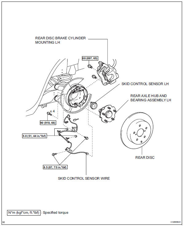
Removal
Hint:
- Use the same procedures for the lh side and rh side.
- The procedures listed below are for the lh side.
- Disconnect cable from negative battery terminal
Caution:
Wait at least 90 seconds after disconnecting the cable from the negative (-) battery terminal to prevent airbag and seat belt pretensioner activation.
- Remove rear wheel
- Remove deck trim side panel assembly lh
- Remove the deck trim side panel lh (see page ir- 26).
Hint:
Refer to the procedures from the removal of the rear door scuff plate lh up until the removal of the deck trim side panel lh.
- Remove skid control sensor wire
- Disconnect the skid control sensor wire connector.

- Disconnect the grommet of the skid control sensor wire from the hole of the wheel house.

- Remove the bolt (labeled a) and sensor clamp (labeled b) from the side member.
- Remove the 2 nuts (labeled c) and sensor clamps (labeled d) from the upper arm.

- Remove the bolt (labeled e) and sensor clamp (labeled f) from the carrier.
- Disconnect the skid control sensor wire connector (labeled g) from the speed sensor.
- Remove rear disc brake cylinder mounting lh (see page br-55)
- Remove rear disc (see page br-57)
- Remove rear axle hub and bearing assembly lh

- Remove the rear axle hub and bearing lh (see page ah-16).
- Remove skid control sensor lh
- Mount the front axle hub in a soft jaw vise.
Notice:
Replace the hub and bearing if it is dropped or receives a strong shock.
- Using a pin punch and hammer, tap out the 2 pins and remove the 2 attachments from sst.
- Using sst and the 2 bolts (diameter: 12 mm; pitch: 1.5 Mm), remove the skid control sensor from the hub and bearing.

Sst 09520-00031 (09520-00040), 09521-00020, 09950-00020
Notice:
- If the sensor rotor is damaged, replace the axle hub.
- Do not scratch the contacting surface of the hub and bearing and skid control sensor.
Inspection
- Inspect skid control sensor
- Check the speed sensor. If any of the following occurs, replace the speed sensor with a new one.
- The surface of the speed sensor is cracked, dented, or chipped.
- The speed sensor has been dropped.
- Inspect skid control sensor wire
- Check the sensor wire. If any of the following
occurs, replace the sensor wire with a new one.
The connector or wire harness is scratched, cracked, or damaged.
Installation
Hint:
- Use the same procedures for the lh side and rh side.
- The procedures listed below are for the lh side.
- Install skid control sensor lh
- Clean the contact surfaces of the axle hub and speed sensor.
Notice:
Make sure the sensor rotor is clean.
- Place the speed sensor on the axle hub so that the connector position is as high as possible when the axle hub is installed to the vehicle.

- Using sst and a press, press the speed sensor into the hub and bearing.
Sst 09214-76011

Notice:
- Do not tap the speed sensor directly with a hammer.
- Check that the speed sensor detection part is clean.
- Press in the speed sensor straight and slowly.
- Install rear axle hub and bearing assembly lh
- Install the rear axle hub and bearing lh (see page ah-18).
- Install rear disc (see page br-58)
- Install rear disc brake cylinder mounting lh (see page br-60)
- Install skid control sensor wire
Notice:
To prevent interference with other parts, do not twist the sensor wire's painted line areas when installing it.
- Connect the skid control sensor wire connector (labeled a) to the speed sensor.
- Install the sensor clamp (labeled b) with the bolt (labeled c).
Torque: 8.5 N*m (87 kgf*cm, 75 in.*Lbf)
Notice:
Do not twist the sensor wire when installing the clamp.

- Install the 2 sensor clamps (labeled d) with the 2 nuts (labeled e).
Torque: 5.0 N*m (51 kgf*cm, 44 in.*Lbf)
Notice:
Do not twist the sensor wire when installing the clamps.
- Install the sensor clamp (labeled f) with the bolt (labeled g).
Torque: 8.5 N*m (87 kgf*cm, 75 in.*Lbf)
Notice:
Do not twist the sensor wire when installing the clamp.

- Insert the connector and grommet to the inside of the vehicle through the hole in the wheel house.
Notice:
Make sure the grommet's band clamp remains on the outside of the vehicle.

- Hold the grommet and pull it from the inside of the vehicle to the outside of the vehicle. Then fix it in place so that it is not tilted.
Notice:
- When pulling out the grommet, do not grip the sensor wire.
- Fix the grommet in place within the range shown in the illustration.
- connect the skid control sensor wire connector.
- Install deck trim side panel assembly lh
- Install the deck trim side panel lh (see page ir-49).
Hint:
Refer to the procedures from the installation of the deck trim side panel lh up until the installation of the rear door scuff plate lh.
- Install rear wheel
Torque: 103 n*m (1,050 kgf*cm, 76 ft.*Lbf)
- Connect cable to negative battery terminal
- Check speed sensor signal
- Check the speed sensor signal (see page bc-28).
 Installation
Hint:
Use the same procedures for the lh side and rh side.
The procedures listed below are for the lh side.
Install speed sensor front lh
Notice:
To prevent interference with other par ...
 Rear speed sensor (for 4wd)
Components
Removal
Hint:
Use the same procedures for the lh side and rh side.
The procedures listed below are for the lh side.
Disconnect cable from negative battery
terminal
Ca ...
Other materials:
Installation
Caution:
Be sure to read the precautionary notices concerning the
srs airbag system before servicing it (see page rs-1).
Install roof side rail bracket lh
Install the bracket with the 2 bolts.
Torque: 14 n*m (143 kgf*cm, 10 ft.*Lbf)
Install curtain shield airbag assembly lh ...
Customization
Customizable features
Your vehicle includes a variety
of electronic features
that can be personalized to
suit your preferences. The
settings of these features
can be changed using the
multi-information display,
navigation/multimedia system,
or at your Toyota
dealer.
Customizing vehicle features
â– ...
Check for intermittent problems
Check for intermittent problems
Hint:
A momentary interruption (open circuit) in the connectors
and/or wire harness between the sensors and ecus can
be detected by using the ecu data list function of an
intelligent tester.
Turn the ignition switch off and connect the
intelligent test ...
