Toyota RAV4 (XA40) 2013-2018 Service Manual: Installation
Hint:
- Use the same procedures for the lh side and rh side.
- The procedures listed below are for the lh side.
- Install speed sensor front lh
Notice:
To prevent interference with other parts, do not twist the sensor wire's painted line areas when installing it.
- Set the sensor body to the knuckle, and then install the sensor with the bolt.
Torque: 8.5 N*m (87 kgf*cm, 75 in.*Lbf)

Notice:
- Keep the sensor tip and sensor installation hole free from foreign matter.
- Firmly insert the sensor body into the knuckle before tightening the bolt.
- After installing the sensor to the knuckle, make sure that there is no clearance between the sensor stay and knuckle. Also make sure that no foreign matter is stuck between the parts.
- To prevent interference between the sensor and magnetic rotor, do not rotate the sensor body during or after the insertion of the sensor body to the knuckle.
- Install the sensor clamp and sensor clip as follows.

- Set the flexible hose clamp on the flexible hose bracket.
- Simultaneously perform the following: 1) hang the hook part of the sensor clamp (labeled a) on the flexible hose bracket (labeled c); and 2) insert the hook part of the sensor clamp (labeled b) into the flexible hose bracket (labeled d).
Notice:
Do not twist the sensor wire when installing the clamp.
- Tighten together the sensor clamp, flexible hose clamp and flexible hose bracket with the bolt (labeled e).
Torque: 18.5 N*m (189 kgf*cm, 14 ft.*Lbf)
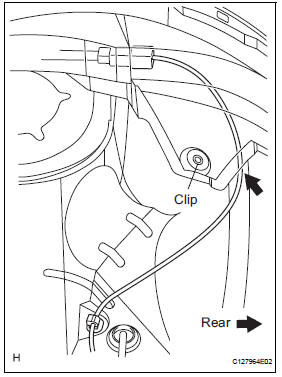
- Insert the sensor clip (labeled f) into the hole on the absorber lower bracket.
- Install the sensor clamp, and sensor clip as follows.
- Set the sensor clamp (labeled g) on the side member, and then tighten it with the bolt (labeled h).
Torque: 8.5 N*m (87 kgf*cm, 75 in.*Lbf)
Notice:
Do not twist the sensor wire when installing the clamp.
- Insert the sensor clip (labeled i) into the hole on the apron.

- Connect the sensor connector.

- Install front fender liner lh
Hint:
Install the fender liner so that the sensor wire harness passes beyond the fender liner installation clip towards the rear side of the vehicle.
- Install front wheel
Torque: 103 n*m (1,050 kgf*cm, 76 ft.*Lbf)
- Connect cable to negative battery terminal
- Check abs speed sensor signal
- Check the speed sensor signal (see page bc-28).
 Installation (2006/01- )
Install abs and traction actuator assembly with bracket
Notice:
do not remove the hole plug before connecting the
brake tube. new actuators are filled with brake fluid.
Install the actuato ...
 Skid control sensor (for 2wd)
Components
Removal
Hint:
Use the same procedures for the lh side and rh side.
The procedures listed below are for the lh side.
Disconnect cable from negative battery
terminal
Ca ...
Other materials:
BSM (Blind Spot Monitor)
The Blind Spot Monitor is a
system that uses rear side
radar sensors installed on
the inner side of the rear
bumper on the left and right
side to assist the driver in
confirming safety when
changing lanes.
WARNING
â– Cautions regarding the use of
the system
The driver is solely responsible
for sa ...
Steering angle sensor circuit malfunction
Description
The steering sensor signal is sent to the skid control ecu via the can
communication system. When
there is a malfunction in the can communication system, it is detected by the
steering sensor zero point
malfunction diagnostic function.
Wiring diagram
Inspection proce ...
Terminals of ecu
Check instrument panel junction block (main body ecu)
Measure the voltage of the connectors.
If the result is not as specified, the junction block
(main body ecu) may have a malfunction. ...
