Toyota RAV4 (XA40) 2013-2018 Service Manual: Short in can bus lines
Description
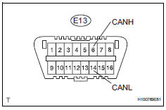
There may be a short circuit between the can bus lines when the resistance
between terminals 6 (canh)
and 14 (canl) of the dlc3 is below 54
 .
.

Wiring diagram


Inspection procedure
Notice:
- Turn the ignition switch off before measuring the resistances of the main wire and the branch wire.
- After the ignition switch is turned off, check that the key reminder warning system and light reminder warning system are not in operation.
- Before measuring the resistance, leave the vehicle for at least 1 minute and do not operate the ignition switch, any switches or doors. If doors need to be opened in order to check connectors, open the doors and leave them open.
Hint:
Operating the ignition switch, any switches or any doors triggers related ecu and sensor communication with the can, which causes resistance variation.
- Check can bus lines for short circuit (dlc3 branch wire)

- Disconnect the e68 no. 2 Junction connector.
- Measure the resistance of the dlc3.
Standard resistance 


- Connect connector
- Reconnect the e68 no. 2 Junction connector.

- Check can bus lines for short circuit (no. 1 Junction connector side)

- Disconnect the a36 no. 1 Junction connector.
- Measure the resistance of the dlc3.
Standard resistance 


- Check can bus lines for short circuit (no. 1 Junction connector - no. 2 Junction connector)

- Disconnect the e68 no. 2 Junction connector.
- Measure the resistance of the wire harness side connector.
Standard resistance


- Connect connector
- Reconnect the a36 no. 1 Junction connector.
- Reconnect the e68 no. 2 Junction connector.

- Check can bus lines for short circuit (no. 3 Junction connector, no. 4 Junction connector side)

- Disconnect the e70 no. 3 Junction connector.
- Measure the resistance of the dlc3.
Standard resistance 


- Connect connector
- Reconnect the e70 no. 3 Junction connector.

- Check can bus lines for short circuit (no. 4 Junction connector side)

- Disconnect the e69 no. 4 Junction connector.
- Measure the resistance of the dlc3.
Standard resistance 


- Check can bus lines for short circuit (no. 3 Junction connector - no. 4 Junction connector)

- Disconnect the e70 no. 3 Junction connector.
- Measure the resistance of the wire harness side connector.
Standard resistance 


- Connect connector
- Reconnect the e69 no. 4 Junction connector.

- Check can bus lines for short circuit (no. 3 Junction connector - center airbag sensor assembly)

- Measure the resistance of the wire harness side connector.
Result 


- Connect connector
- Reconnect the e70 no. 3 Junction connector.

- Check can bus lines for short circuit (center airbag sensor assembly)

- Disconnect the e45 center airbag sensor connector.
- Measure the resistance of the dlc3.
Standard resistance 


Replace center airbag sensor assembly
- Check can bus lines for short circuit (no. 1 Junction connector - ecm)

- Measure the resistance of the wire harness side connector.
Result 


- Check can bus lines for short circuit (no. 1 Junction connector - abs and traction actuator)

- Measure the resistance of the wire harness side connector.
Result 


Repair or replace no. 1 Junction connector
- Connect connector
- Reconnect the a36 no. 1 Junction connector.

- Check can bus lines for short circuit (ecm)

- Disconnect the a9 ecm connector.
- Measure the resistance of the dlc3.
Standard resistance 


Replace ecm
- Connect connector
- Reconnect the a36 no. 1 Junction connector.

- Check can bus lines for short circuit (abs and traction actuator)

- Disconnect the a19 abs and brake actuator (skid control ecu) connector.
- Measure the resistance of the dlc3.
Standard resistance 

Replace abs and traction actuator (skid control ecu)
- Connect connector
- Reconnect the e70 no. 3 Junction connector.

- Check can bus lines for short circuit (no. 2 Junction connector - yaw rate sensor)

- Disconnect the e68 no. 2 Junction connector.
- Measure the resistance of the wire harness side connector.
Result 


- Check can bus lines for short circuit (no. 2 Junction connector - power steering ecu)

- Measure the resistance of the wire harness side connector.
Result


- Check can bus lines for short circuit (no. 2 Junction connector - main body ecu)

- Measure the resistance of the wire harness side connector.
Result 


- Check can bus lines for short circuit (no. 2 Junction connector - air conditioning amplifier)

- Measure the resistance of the wire harness side connector.
Result 


- Check can bus lines for short circuit (no. 2 Junction connector - steering angle sensor)

- Measure the resistance of the wire harness side connector.
Result 


Repair or replace no. 2 Junction connector
- Connect connector
- Reconnect the e68 no. 2 Junction connector.

- Check can bus lines for short circuit (yaw rate sensor)

- Disconnect the k6 yaw rate sensor connector.
- Measure the resistance of the dlc3.
Standard resistance 


Replace yaw rate sensor
- Connect connector
- Reconnect the e68 no. 2 Junction connector.

- Check can bus lines for short circuit (power steering ecu)

- Disconnect the e18 power steering ecu connector.
- Measure the resistance of the dlc3.
Standard resistance 


Replace power steering ecu
- Connect connector
- Reconnect the e68 no. 2 Junction connector.

- Check can bus lines for short circuit (main body ecu)

- Disconnect the e17 main body ecu connector.
- Measure the resistance of the dlc3.
Standard resistance 


Replace instrument panel junction block (main body ecu)
- Connect connector
- Reconnect the e68 no. 2 Junction connector.

- Check can bus lines for short circuit (air conditioning amplifier)

- Disconnect the e37*1 or e36*2 air conditioning amplifier connector.
Hint:
- *1: For automatic air conditioning system.
- *2: For manual air conditioning system.
- Measure the resistance of the dlc3.
Standard resistance 


Replace air conditioning amplifier
- Connect connector
- Reconnect the e68 no. 2 Junction connector.

- Check can bus lines for short circuit (steering angle sensor)
- Disconnect the e11 steering sensor connector.
- Measure the resistance of the dlc3.
Standard resistance 


Replace steering angle sensor
- Check can bus lines for short circuit (no. 4 Junction connector - 4wd control ecu)

Notice:
For vehicles without 4wd, go to "check can bus lines for short circuit (no. 4 Junction connector - combination meter ecu)".
- Measure the resistance of the wire harness side connector.
Result 


- Check can bus lines for short circuit (no. 4 Junction connector - combination meter ecu)

- Measure the resistance of the wire harness side connector.
Result 


Repair or replace no. 4 Junction connector
- Connect connector
- Reconnect the e69 no. 4 Junction connector.

- Check can bus lines for short circuit (4wd control ecu)

- Disconnect the e57 4wd control ecu connector.
- Measure the resistance of the dlc3.
Standard resistance 


Replace 4wd control ecu
- Connect connector
- Reconnect the e69 no. 4 Junction connector.

- Check can bus lines for short circuit (combination meter ecu)

- Disconnect the e19 combination meter ecu connector.
- Measure the resistance of the dlc3.
Standard resistance 


Replace combination meter ecu
 Open in can main wire
Description
There may be an open circuit in the can main wire and / or the dlc3 branch
wire when the resistance
between terminals 6 (canh) and 14 (canl) of the dlc3 is 69 ù or more.
Wi ...
 Short to b+ in can bus line
Description
There may be a short circuit between the can bus line and +b when there is
resistance between
terminals 6 (canh) and 16 (bat) or terminals 14 (canl) and 16 (bat) of the dlc3.
Wiri ...
Other materials:
Bluetooth®
When using the bluetooth® audio system
In the following conditions, the system may not function.
If the portable audio player is turned off
If the portable audio player is not connected
If the portable audio player’s battery is low
There may be a delay if a cellular phone connection i ...
Driver side - side airbag sensor circuit malfunction
Description
The side airbag sensor lh consists of part including the diagnostic circuit
and the lateral deceleration
sensor.
When the center airbag sensor receives signals from the lateral deceleration
sensor, it determines
whether or not the srs should be activated.
Dtc b1620/21 is ...
Removal
Disconnect cable from negative battery
terminal
Caution:
Wait at least 90 seconds after disconnecting the
cable from the negative (-) battery terminal to
prevent airbag and seat belt pretensioner activation.
Disconnect cable from positive battery
terminal
Remove battery clamp
...
