
Toyota RAV4 (XA40) 2013-2018 Service Manual: Removal
- Discharge fuel system pressure (see page fu-9)
- Drain coolant (see page co-6)
- Disconnect cable from negative battery terminal
Caution:
Wait at least 90 seconds after disconnecting the cable from the negative (-) battery terminal to prevent airbag and seat belt pretensioner activation.
- Remove no. 1 Engine cover (see page es-410)
- Remove air cleaner cap (see page es-411)
- Remove throttle body (see page es-412)
- Remove fuel delivery pipe (see page fu-10)
- Disconnect fuel tube
- Remove heater water inlet hose
- Remove the hose clamp.
- Remove the heater water inlet hose from the heater radiator unit and cylinder head.
- Remove heater water outlet hose
- Remove the heater water outlet hose from the heater radiator unit and water by-pass pipe.
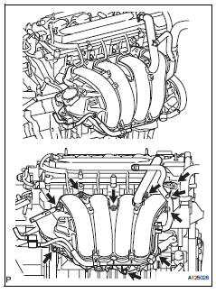
- Remove intake manifold
- Disconnect the union to check valve hose from the brake booster.
- Disconnect the camshaft timing oil control valve connector.
- Remove the wire harness clamp.
- Remove the union to check valve hose from the vacuum hose clamp.
- Remove the 5 bolts, 2 nuts and intake manifold.
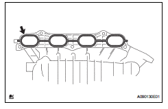
- Remove the gasket from the intake manifold.
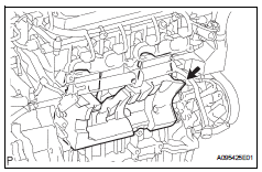
- Remove intake manifold insulator
- Remove the intake manifold insulator from the cylinder block.
- Remove knock sensor
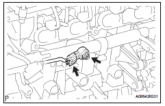
- Disconnect the sensor connector.
- Remove the nut and sensor.
 Components
...
 Inspection
Inspect knock sensor
Measure the resistance of the sensor.
Standard resistance
If the result is not as specified, replace the knock
sensor. ...
Other materials:
Removal (2006/01- )
Disconnect cable from negative battery
terminal
Caution:
Wait at least 90 seconds after disconnecting the
cable from the negative (-) battery terminal to
prevent airbag and seat belt pretensioner activation.
Remove air cleaner case sub-assembly (for
2az-fe)
Remove the air clea ...
Removal
Disconnect cable from negative battery
terminal
Caution:
Wait at least 90 seconds after disconnecting the
cable from the negative (-) battery terminal to
prevent airbag and seat belt pretensioner activation.
Remove rear door scuff plate rh (see page
ir-29)
Remove package tray trim ...
Folding the mirrors
Push the mirror back in the direction
of the vehicle’s rear.
Mirror angle can be adjusted when
Vehicles without a smart key system
The engine switch is in the “acc� or “on� position.
Vehicles with a smart key system
The engine switch is in accessory or ignition on mode. ...
