Toyota RAV4 (XA40) 2013-2018 Service Manual: Rear bumper
Components

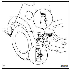
Removal
- Remove rear bumper cover

- Remove the 9 screws and 7 clips.
- Put protective tape under the quarter panel.
- Detach the 12 claws and remove the bumper cover.
- Remove rear bumper protector

Hint:
When removing the bumper protector, heat the bumper protector.
Standard heating temperature


- Using a moulding remover, remove the bumper protector.
- Remove reflex reflector assembly lh
- Remove the screw and reflex reflector.
- Remove reflex reflector assembly rh

Hint:
Use the same procedures described for the lh side.
- Remove rear bumper reinforcement

- Remove the 6 bolts and reinforcement.
- Remove rear bumper side support lh

- Remove the 2 screws.
- Using a screwdriver, detach the claw and remove the bumper side support.
Hint:
Tape the screwdriver tip before use.
- Remove rear bumper side support rh
Hint:
Use the same procedures described for the lh side.
- Remove rear bumper side retainer lh
- Remove the screw.
- Using a screwdriver, detach the claw and remove the side retainer.
Hint:
Tape the screwdriver tip before use.
- Remove rear bumper side retainer rh
Hint:
Use the same procedures described for the lh side.

- Remove rear bumper side moulding subassembly lh (for wide body)

- Detach the 5 outside moulding retainers and remove the moulding.
Notice:
- If reusing the extension, take care not to damage the moulding.
- Be careful not to damage the vehicle body.
- Remove rear bumper side moulding subassembly rh (for wide body)
hint:
Use the same procedures described for the lh side.
Installation
- Install rear bumper side moulding subassembly lh (for wide body)
- Attach the 5 outside moulding retainers to install the moulding.
- Install rear bumper side moulding subassembly rh (for wide body)
Hint:
Use the same procedures described for the lh side.

- Install rear bumper side retainer lh
- Attach the claw to install the side retainer.
- Install the screw.
- Install rear bumper side retainer rh
Hint:
Use the same procedures described for the lh side.
- Install rear bumper side support lh
- Attach the claw to install the bumper side support.
- Install the 2 screws.
- Install rear bumper side support rh
Hint:
Use the same procedures described for the lh side.

- Install rear bumper reinforcement

- Install the bumper reinforcement with the 6 bolts.
Torque: 37 n*m (377 kgf*cm, 27 ft.*Lbf)
- Install reflex reflector assembly lh
- Install the reflex reflector with the screw.

- Install reflex reflector assembly rh
Hint:
Use the same procedures described for the lh side.
- Install rear bumper protector
Hint:
When removing the double-side tape, heat the rear bumper.
Standard heating temperature

- Clean the bumper surface.
- Using a heat light, heat the bumper surface.
- Remove the double-sided tape from the bumper.
- Wipe off any tape adhesive residue with cleaner.
- Install the new bumper protector.

Install rear bumper cover

- Put protective tape under the quarter panel.
- Attach the 12 claws to install the bumper cover.

- Install the 9 screws and 7 clips.
 Installation
Install front bumper side retainer lh
Install the clip and bumper side retainer.
Install the bolt.
Torque: 6.0 N*m (61 kgf*cm, 53 in.*Lbf)
Install front bumper side retainer rh
...
 Radiator grille
Components
Removal
Remove radiator grille (see page et-6)
Remove no. 1 Radiator grille lower (see
page et-7)
Remove no. 2 Radiator grille lower (see
page et-7)
...
Other materials:
Auto lsd indicator light remains on
Description
This is the auto lsd switch for 2wd. When the auto lsd switch is pushed on,
the auto lsd function is
available and the auto lsd indicator light illuminates.
Hint:
The auto lsd does not operate even if the auto lsd switch is pressed under
the following conditions:
The trc or v ...
Cruise control switch circuit
Description
This circuit sends signals to the ecm depending on the cruise control switch
condition. The battery
supplies positive (+) battery voltage to the cruise control switch. Then
terminal ccs of the ecm receives
the voltage according to the switch condition.
Wiring diagram
Inspect ...
Diaphragm oil seal
Components
Removal
Drain differential oil
Using a 10 mm socket hexagon wrench, remove the
rear differential drain plug and gasket, and drain the
oil.
Install a new gasket to the rear differential drain
plug.
Using a 10 mm socket hexagon wrench, install the
rear differe ...
