Toyota RAV4 (XA40) 2013-2018 Service Manual: Installation (2006/01- )
- Install front drive shaft assembly lh
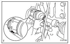
- Coat the spline of the inboard joint shaft with gear oil.
- Align the shaft splines and tap in the drive shaft with a brass bar and hammer.
Notice:
- Set the snap ring with the opening side facing downwards.
- Be careful not to damage the oil seal, boot and dust cover.
- Install front drive shaft assembly rh

- Coat the spline of the inboard joint shaft with gear oil.
- Align the shaft splines and securely insert the drive shaft.
- Install the 2 bearing bracket bolts.
Torque: 63.7 N*m (650 kgf*cm, 47 ft.*Lbf)
Notice:
Do not damage the oil seal, boot and dust cover.
- Connect steering knuckle with axle hub lh

- Align the shaft splines in the drive shaft to the steering knuckle with axle hub, and connect the steering knuckle with axle hub.
- Connect steering knuckle with axle hub rh
Hint:
Use the same procedures described for the lh side.
- Connect front suspension no. 1 Lower arm sub-assembly lh (see page sp-24)
- Connect front suspension no. 1 Lower arm sub-assembly rh
Hint:
Use the same procedures described for the lh side.
- Install front stabilizer link assembly lh (see page sp-31)
- Install front stabilizer link assembly rh
Hint:
Use the same procedures described for the lh side.
- Connect tie rod end sub-assembly lh (see page ps-45)
- Connect tie rod end sub-assembly rh
Hint:
Use the same procedures described for the lh side.
- Connect front speed sensor lh
- Connect the speed sensor (see page bc-193).
- Install front speed sensor rh
Hint:
Use the same procedures described for the lh side.
- Install front axle hub nut (see page ah-11)
- Install front wheel torque: 103 n*m (1,050 kgf*cm, 76 ft.*Lbf)
- Add automatic transaxle fluid
- Add automatic transaxle fluid for u140f (see page ax-152).
- Add automatic transaxle fluid for u241e (see page ax-151).
- Add automatic transaxle fluid for u151e (see page ax-177).
- Check for automatic transaxle oil leakage
- Inspect and adjust front wheel alignment
- Inspect and adjust the front wheel alignment (see page sp-3).
 Installation (2005/11-2006/01)
Install front drive shaft assembly lh
Coat the spline of the inboard joint shaft with gear
oil.
Using a brass bar and hammer, align the shaft
splines in the drive shaft.
Notice:
...
 Front drive shaft assembly (for 4wd)
Components (2005/11-2006/01)
Components (2006/01- )
...
Other materials:
Brake front brake flexible hose
Components
Removal
Hint:
Use the same procedures for the lh side and rh side.
The procedures listed below are for the lh side.
Remove front wheel
Drain brake fluid
Notice:
Wash off brake fluid immediately if it comes in
contact with any painted surface.
Remove front flex ...
Hitch
Trailer hitch assemblies have different weight capacities. Toyota recommends
the use of toyota hitch/bracket for your vehicle. For details,
contact your toyota dealer.
If you wish to install a trailer hitch, contact your toyota dealer.
Use only a hitch that conforms to the gross trailer weig ...
Driving information display
Select to display fuel consumption
data in various forms.
â– Fuel Economy
Following information is displayed.
Distance to empty
Displays the driving range with
remaining fuel.
Current fuel economy
Displays the instantaneous current
fuel Economy.
Average fuel economy
Displays the average f ...
