Toyota RAV4 (XA40) 2013-2018 Service Manual: Fuel pressure pulsation damper
Components


Removal
- Discharge fuel system pressure (see page fu-9)
- Disconnect cable from negative battery terminal
- Remove no. 1 Engine cover (see page es-410)
- Remove air cleaner cap sub-assembly (see page es-411)
- Disconnect fuel main tube (see page fu-10)
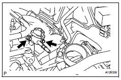
- Remove fuel pressure pulsation damper assembly

- Remove the 2 bolts and fuel pressure pulsation damper.
Installation
- Install fuel pressure pulsation damper assembly

- Apply a light coat of gasoline or spindle oil to the oring of the fuel pressure pulsation damper.
- Install the fuel pressure pulsation damper with the 2 bolts.
Torque: 9.0 N*m (90 kgf*cm, 80 in.*Lbf)
Notice:
Make sure that the o-ring is not cracked or jammed when installing.
- Install fuel main tube (see page fu-14)
- Install air cleaner cap sub-assembly (see page es-413)
- Install no. 1 Engine cover (see page es-414)
- Connect cable to battery negative terminal
- Check for fuel leaks (see page fu-14)
 Fuel pressure regulator
Components
Removal
Remove fuel tank assembly
Remove the fuel tank (see page fu-39).
Remove fuel tank main tube sub-assembly
Remove the joint clip and fuel tank main tube ...
 Fuel pump
Components
Removal
Remove fuel tank assembly
Remove the fuel tank (see page fu-39).
Remove fuel tank main tube sub-assembly
Remove the joint clip and fuel tank main tube ...
Other materials:
Communication
Description
The skid control ecu sends signals such as cruise control cancel demand
signals and brake operation
demand from ecm response signals to the ecm when the cruise control system is in
operation.
Inspection procedure
Hint:
This circuit uses can communication. Therefore, if t ...
Assist map number un-writing
Description
The power steering ecu outputs this dtc when it determines that the assist
map is not written in the
ecu.
Hint:
The assist map data is written in the power steering ecu to control assisting
power.
The assist map has 3 types. Select an assist map according to the vehicle
...
Fuel consumption information
The fuel consumption information
can be displayed on
the Multimedia Display.
Display procedure
Press on the main menu,
then press "Trip information" on
the sub menu.
For detail regarding the Multimedia
Display, refer to "MULTIMEDIA
OWNER'S MANUAL".
â– Current fuel consumption
screen
If a screen o ...
