Toyota RAV4 (XA40) 2013-2018 Service Manual: Direct clutch
Components

Disassembly
- Inspect pack clearance of direct clutch (see page ax-234)
- Remove direct multiple disc clutch disc
- Using a screwdriver, pry out the snap ring from the direct clutch drum.

- Remove the flange, 3 discs and 3 plates from the direct clutch drum.

- Inspect direct multiple disc clutch disc (see page ax-234)
- Remove direct clutch return spring subassembly

- Place sst on the clutch balancer and compress the spring with a press.
Sst 09387-00020
- Using a snap ring expander, remove the snap ring from the direct clutch drum.
Notice:
- Stop the press when the spring sheet is lowered to the place 1 to 2 mm (0.039 To 0.078 In.) From the snap ring groove.
- This prevents the spring sheet from being deformed.
- Do not expand the snap ring excessively.

- Remove the clutch balancer from the direct clutch drum.

- Remove the piston return spring from the direct clutch drum.

- Install the direct clutch drum on the transaxle rear cover.
- Holding the direct clutch piston with your hand, apply compressed air (392 kpa, 4.0 Kgf*cm2, 57 psi) to the transaxle rear cover to remove the direct clutch piston.
Inspection
- Inspect pack clearance of direct clutch

- Install the direct clutch and needle roller bearing on the transaxle rear cover.
- Using a dial indicator, measure the forward clutch pack clearance while applying and releasing compressed air (392 kpa, 4.0 Kgf/cm2, 57 psi)
Standard pack clearance: 0.515 To 0.825 Mm (0.0203 To 0.0324 In.)
If the pack clearance is not as specified, inspect the discs, plates and flange.
- Inspect direct multiple disc clutch disc

- Check to see if the sliding surface of the disc, plate
and flange are worn or burnt.
If necessary, replace them.
Hint:
- If the lining of the disc is peeling off or discolored, or even if a part of the printed mark is defaced, replace all discs.
- Before assembling new discs, soak them in atf for at least 15 minutes.
- Inspect direct clutch return spring subassembly

- Using a vernier caliper, measure the free length of
the spring together with the spring seat.
Standard free length: 22.58 Mm (0.8898 In.)
Reassembly
- Install direct clutch return spring subassembly

- Coat the direct clutch piston with atf, and install it to the direct clutch drum.
Notice:
Be careful not to damage the lip seal of the direct clutch piston.
- Install the piston return spring to the direct clutch drum.

- Install the clutch balancer to the direct clutch drum.
Notice:
Be careful not to damage the lip seal of the direct clutch balancer.

- Place sst on the clutch balancer and compress the piston return spring with a press.
Sst 09387-00020
- Using a snap ring expander, install the snap ring to the direct clutch drum.
Notice:
- Be sure the end gap of the snap ring is not aligned with the clutch balancer claw.
- Stop the press when the spring sheet is lowered to the place 1 to 2 mm (0.039 To 0.078 In.) From the snap ring groove.
- This prevents the spring sheet from being deformed.
- Do not expand the snap ring excessively.
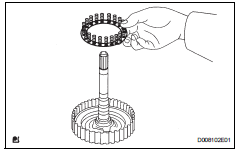
- Install direct multiple disc clutch disc

- Install the 3 plates, 3 discs and flange to the direct clutch drum.
Install in order: p - d - p - d - p - d - f
Hint:
P = plate
D = disc
F = flange

- Using a screwdriver, install the snap ring.
- Check that the end gap of the snap ring is not aligned with one of the cutouts.
- Inspect pack clearance of direct clutch

- Install the direct clutch on the transaxle rear cover.
- Using a dial indicator, measure the direct clutch pack clearance while applying and releasing compressed air (392 kpa, 4.0 Kgf/cm2, 57 psi).
Standard pack clearance: 0.515 To 0.825 Mm (0.0203 To 0.0324 In.)
If the pack clearance is less than the minimum, parts may have been assembled incorrectly, so check and reassemble again.
If the stroke is not as specified, select another flange.
Hint:
There are 6 flanges in different thickness.
Standard flanges in different thickness

- Inspect direct multiple disc clutch disc

- Check that the disc rotates when rotating the disc after inserting the rear planetary sun gear.
Notice:
Do not place the rear planetary sun gear in a vise.
 Forward clutch
Components
Disassembly
Inspect forward clutch (see page ax-227)
Remove forward multiple disc clutch disc
Using a screwdriver, remove the snap ring.
Remove the flange , 5 discs a ...
 Underdrive planetary gear
Components
Disassembly
Remove underdrive planetary gear
preload (see page ax-240)
Remove underdrive input shaft nut
Sst 09930-00010 (09931-00010, 09931-00020),
09387-00050, 09564-1602 ...
Other materials:
Turn signal light circuit
Description
The turn signal flasher relay (marking: flsh) in the main body ecu turns on
when it receives signals
from the headlight dimmer switch integrated with the turn signal switch, causing
the turn signal lights to
flash.
Wiring diagram
Inspection procedure
Check operation of t ...
Evaporative emission control system leak detected
Dtc summary
Description
The description can be found in the evap (evaporative emission) system (see
page es-335).
Inspection procedure
Refer to the evap system (see page es-340).
Monitor description
5 Hours* after the ignition switch is turned off, the leak detection pump
creates n ...
Power mirror control system
Parts location
System diagram
System description
The outer mirror switch controls the outer rear view mirror lh
and rh.
Problem symptoms table
Hint:
Use the table below to help determine the cause of the
problem symptom. The potential causes of the symptoms are
listed in order of pr ...
