Toyota RAV4 (XA40) 2013-2018 Service Manual: Canister
Components

removal
- Disconnect cable from negative battery terminal
Caution:
Wait at least 90 seconds after disconnecting the cable from the negative (-) battery terminal to prevent airbag and seat belt pretensioner activation.
- Remove canister
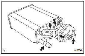
- Disconnect the 2 tubes, hose and connector.

- Using a screwdriver, pry up the retainer.
Hint:
Do not remove the retainer.
- Disconnect the purge line hose.
- Disconnect the air inlet line tube from the canister.
- Disconnect the vent line tube from the canister (leak detection pump).
- Disconnect the connector from the canister (leak detection pump).
Notice:
Remove any dirt or foreign objects on the fuel tube connector before performing this work.

- Do not allow any scratches or foreign objects on the parts when disconnecting as the fuel tube connector has the o-ring that seals the pipe.
- Perform this work by hand. Do not use any tools.
- Do not forcibly bend, twist or turn the nylon tube.
- Protect the disconnected part by covering it with a plastic bag after disconnecting the fuel tank vent hose.
- If the fuel tube connector and pipe are stuck, push and pull to release them.

- Remove the 4 bolts, clip and canister.
Inspection
- Inspect canister
- Visually check the canister for cracks or damage.
If cracks or damage is found, replace the canister.

- While holding the purge port closed, blow air
0.39 Kpa (4.0 Kgf/cm2, 3 mmhg) into the vent
port, and check that air flows from the air inlet
port.
If the result is not as specified, replace the canister.

- While holding the air inlet port closed, blow air
0.39 Kpa (4.0 Kgf/cm2, 3 mmhg) into the vent
port, and check that air flows from the purge
port.
If the result is not as specified, replace the canister.

- While holding the air inlet port closed, apply
vacuum 3.43 Kpa (35.0 Kgf/cm2, 25.7 Mmhg)
to the vent port, and check that air is sucked
into the purge port.
If the result is not as specified, replace the canister.
- Check the air tightness.

- While holding the vent and air inlet ports
closed, apply vacuum 3.43 Kpa (35.0 Kgf/cm2,
25.7 Mmhg) to the purge port, and check that
the vacuum is maintained for 1 minute.
If the result is not as specified, replace the canister.
- Check the diaphragm.

- Remove the air hose between ports a and b.
- While holding the vent, purge and air inlet ports closed, apply vacuum 1.42 Kpa (14.5 Kgf/cm2, 10.6 Mmhg) to port a, and check that air is not sucked into port b.
- While holding the vent, purge and air inlet ports Closed, apply vacuum 1.42 Kpa (14.5 Kgf/cm2, 10.6 Mmhg) to port a, and measure how long it takes for the vacuum to drop.

Vacuum drop time: 10 seconds or more
If the result is not as specified, replace the canister.
- Check the leak detection pump.

- Check that air flows from port a to port b and
c.
If the result is not as specified, replace the canister.
- Connect the positive (+) lead of the battery to terminal 7 and the negative (-) lead to terminal 6.
- Check that the valve is closed.
If the result is not as specified, replace the canister.
- Install the canister pump module.

Installation
- Install canister
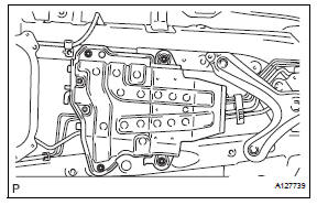
- install the canister with the 4 bolts and clip.
torque: 20 n*m (204 kgf*cm, 15 ft.*lbf)
- Connect the air inlet line tube to the canister (leak detection pump).
- Install the vent line tube.

- Connect the pipe to the fuel tube connector, as shown in a in the illustration. Then push up the retainer to lock the claws, as shown in b in the illustration.
Notice:
- Check that there are no scratches or foreign objects around the connected part of the fuel tube connector and pipe before performing this work.
- After connecting the fuel tank vent tube, check that the fuel tank vent tube is securely connected by pulling the fuel tube connector and pipe.
- Connect the purge line hose.
Hint:
Install the hose to the canister, and then attach the retainer.
- Connect the connector to the canister (leak detection pump).
- Connect cable to negative battery terminal
 Emission control system
Parts location
System diagram
On-vehicle inspection
Check fuel cut rpm
Increase the engine speed to at least 3,500 rpm.
Use a sound scope to check for injecto ...
 Vacuum switching valve
Components
Removal
Disconnect cable from negative battery
terminal
Caution:
Wait at least 90 seconds after disconnecting the
cable from the negative (-) battery terminal to
prevent ai ...
Other materials:
Cruise control system cruise control main switch
Components
Removal
Caution:
Be sure to read the precautionary notices concerning the
srs airbag system before servicing it (see page rs-1).
Disconnect cable from negative battery
terminal
Caution:
Wait at least 90 seconds after disconnecting the
cable from the negative (-) batt ...
Oxygen (a/f) sensor signal stuck
Hint:
Although the dtc titles say oxygen sensor, these dtcs relate to the
air-fuel ratio (a/f) sensor.
Sensor 1 refers to the sensor mounted in front of the three-way
catalytic converter (twc) and
located near the engine assembly.
Description
The a/f sensor generates a voltage* ...
Utility vehicle
precautions
This vehicle belongs to the utility vehicle class, which has
higher ground clearance and narrower tread in relation to the
height of its center of gravity to make it capable of performing in
a wide variety of off-road applications.
Utility vehicle feature
Specific design characteristics give ...
