Toyota RAV4 (XA50) 2019-2025 Owners Manual: BSM (Blind Spot Monitor)
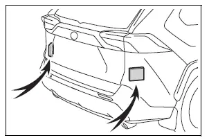
The Blind Spot Monitor is a system that uses rear side radar sensors installed on the inner side of the rear bumper on the left and right side to assist the driver in confirming safety when changing lanes.
WARNING
â– Cautions regarding the use of the system
- The driver is solely responsible for safe driving. Always drive safely, taking care to observe your surroundings.
- The Blind Spot Monitor is a supplementary function which alerts the driver that a vehicle is in a blind spot of the outside rear view mirrors or is approaching rapidly from behind into a blind spot. Do not overly rely on the Blind Spot Monitor. As the function cannot judge if it is safe to change lanes, over reliance could lead to an accident resulting in death or serious injury. As the system may not function correctly under certain conditions, the driver's own visual confirmation of safety is necessary.
System components
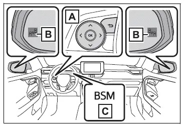
- Meter control switches Turning the Blind Spot Monitor on/off.
- Outside rear view mirror indicators
When driving:
When a vehicle is detected in a blind spot of the outside rear view mirrors or approaching rapidly from behind into a blind spot, the outside rear view mirror indicator on the detected side will illuminate. If the turn signal lever is operated toward the detected side, the outside rear view mirror indicator flashes. - "BSM" indicator
When the BSM function is turned on, the indicator illuminates.
â– Outside rear view mirror indicator visibility
In strong sunlight, the outside rear view mirror indicator may be difficult to see.
â– When "Blind Spot Monitor Unavailable" is shown on the multi-information display
Ice, snow, mud, etc., may be attached to the rear bumper around the sensors. The system should return to normal operation after removing the ice, snow, mud, etc. from the rear bumper. Additionally, the sensors may not operate normally when driving in extremely hot or cold environments.
â– When "Blind Spot Monitor Malfunction Visit Your Dealer" is shown on the multi-information display
There may be a sensor malfunction of misaligned. Have the vehicle inspected by your Toyota dealer.
â– Customization
Some functions can be customized.
WARNING
â– To ensure the system can operate properly
Blind Spot Monitor sensors are installed behind the left and right sides of the rear bumper respectively.
Observe the following to ensure the Blind Spot Monitor can operate correctly.
- Keep the sensors and the surrounding
areas on the rear
bumper clean at all times.
If a sensor or its surrounding area on the rear bumper is dirty or covered with snow, the Blind Spot Monitor may not operate and a warning message will be displayed. In this situation, clear off the dirt or snow and drive the vehicle with the operation conditions of the BSM function satisfied for approximately 60 minutes.
If the warning message does not disappear, have the vehicle inspected by your Toyota dealer.
- Do not attach accessories, stickers (including transparent stickers), aluminum tape, etc. to a sensor or its surrounding area on the rear bumper.
- Do not subject a sensor or its
surrounding area on the rear
bumper to a strong impact.
If a sensor is moved even slightly off position, the system may malfunction and vehicles may not be detected correctly.
In the following situations, have your vehicle inspected by your Toyota dealer.
- A sensor or its surrounding area is subject to a strong impact.
- If the surrounding area of a sensor is scratched or dented, or part of them has become disconnected.
- Do not disassemble the sensor.
- Do not modify the sensor or surrounding area on the rear bumper.
- If a sensor or the rear bumper needs to be removed/installed or replaced, contact your Toyota dealer.
- Do not paint the rear bumper any color other than an official Toyota color.
Turning the Blind Spot Monitor on/off
The Blind Spot Monitor  can
can
be enabled/disabled on  of
of
the multi-information display.
When the Blind Spot Monitor is enabled, the BSM indicator will illuminate.
 Canceling and resuming
the speed control
Canceling and resuming
the speed control
Pressing the cancel switch
cancels the speed control.
The speed control is also canceled
when the brake pedal is depressed.
(When the vehicle has been
stopped by system control,
depressing the b ...
 Blind Spot Monitor operation
â– Objects that can be detected while driving
The Blind Spot Monitor uses rear side radar sensors to detect the
following vehicles traveling in adjacent lanes and advises the driver
of the presence o ...
Other materials:
Traction control switch (for 2wd)
Components
Removal
Disconnect cable from negative battery
terminal
Caution:
Wait at least 90 seconds after disconnecting the
cable from the negative (-) battery terminal to
prevent airbag and seat belt pretensioner activation.
Remove traction control switch (auto lsd switch)
...
Cruise control system cruise control main switch
Components
Removal
Caution:
Be sure to read the precautionary notices concerning the
srs airbag system before servicing it (see page rs-1).
Disconnect cable from negative battery
terminal
Caution:
Wait at least 90 seconds after disconnecting the
cable from the negative (-) batt ...
Installation
Install camshaft timing oil control valve
assembly
Apply a light coat of engine oil to the o-ring of the oil
control valve.
Install the oil control valve with the bolt.
Torque: 9.0 N*m (92 kgf*cm, 80 in.*Lbf)
Notice:
Make sure that the o-ring is not cracked or
jammed.
Co ...
