Toyota RAV4 (XA40) 2013-2018 Service Manual: Air fuel ratio sensor
Components
On-vehicle inspection
- Check air fuel ratio compensation system
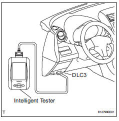
- Connect the intelligent tester to the dlc3.
- Turn the ignition switch on.
- Select the following menu items: data list / a/fs b1 s1 and o2s b1 s2.
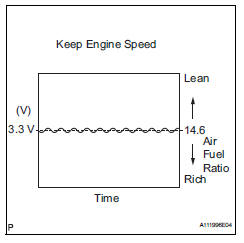
- Warm up the a/f sensor with the engine speed at 2,500 rpm for approximately 2 minutes.
- Keep the engine speed at 2,500 rpm and confirm that the display of "a/fs b1 s1" is as shown in the illustration.
Hint:
- The illustration may slightly differ from the display on the intelligent tester.
- Only the intelligent tester displays the waveform of the a/f sensor.
- Confirm that the display of "o2s b1 s2" changes between 0 to 1 v with the engine speed at 2,500 rpm.
Ok: the voltage output oscillates more than 8 times in 10 seconds.
Notice:
- Perform the check immediately after warming the engine up.
- If the voltage variation could not be verified, warm up the a/f sensor again. If it could not be verified even after warming up the sensor again, check for dtcs (see page es-292).
Removal
- Disconnect cable from negative battery terminal
Caution:
Wait at least 90 seconds after disconnecting the cable from the negative (-) battery terminal to prevent airbag and seat belt pretensioner activation.
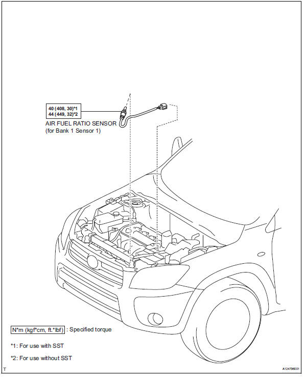
- Remove air fuel ratio sensor (for bank 1 sensor 1)
- Disconnect the sensor connector.
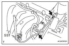
- Using sst, remove the sensor from the exhaust manifold.
Sst 09224-00010
Inspection
- Inspect air fuel ratio sensor (for bank 1 sensor 1)
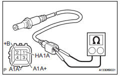
- Measure the resistance of the sensor.
Standard resistance 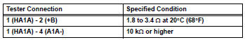
If the resistance is not as specified, replace the sensor.
Installation
- Install air fuel ratio sensor (for bank 1 sensor 1)
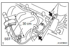
- Using sst, install the sensor to the exhaust manifold.
Sst 09224-00010
Torque: 40 n*m (408 kgf*cm, 30 ft.*Lbf) for use with sst
44 N*m (449 kgf*cm, 32 ft.*Lbf) for use without sst
Hint:
- Use a torque wrench with a fulcrum length of 30 cm (11.81 In.).
- Make sure sst and wrench are connected in a straight line.
- Connect the sensor connector.
- Connect cable to negative battery terminal
- Check for exhaust gas leaks
 Ventilation valve
Components
Removal
Remove no. 1 Engine cover (see page em-22)
Remove ventilation valve sub-assembly
Disconnect the ventilation hose from the ventilation
valve.
Using a ...
 Heated oxygen sensor
Components
Removal
Disconnect cable from negative battery
terminal
Caution:
Wait at least 90 seconds after disconnecting the
cable from the negative (-) battery terminal to
prevent ai ...
Other materials:
Installation with latch system
Adjust the seatback to the 8th
lock position from the fully
reclined position.
Fully reclined position
8Th lock position
If your child restraint system interferes with a head restraint and
cannot be installed properly, install the child restraint system after
removing the hea ...
Driver side seat belt warning light does not operate
Description
When the ignition switch is on, the center airbag sensor transmits front seat
inner belt status signals to
the combination meter through the can bus line. If the driver seat belt is not
fastened, the combination
meter blinks the driver side seat belt warning light. If the seat bel ...
Propeller shaft assembly
Components
Removal
Remove propeller shaft with center bearing
shaft assembly
Remove the 2 bolts and 2 adjusting washers, and
disconnect the propeller with center bearing shaft.
Notice:
During the removal, do not exert excessive
force on the universal joint.
When r ...
