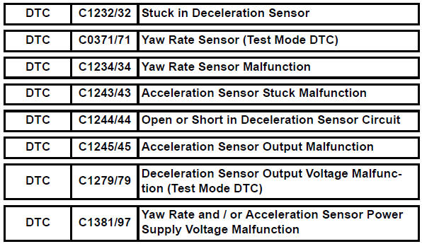
Toyota RAV4 (XA40) 2013-2018 Service Manual: Stuck in deceleration sensor
Description
The skid control ecu receives signals from the yaw rate and deceleration sensor via the can communication system.
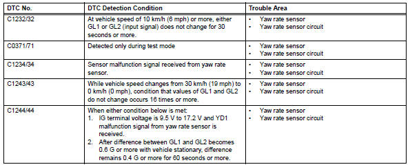
The yaw rate sensor has a built-in deceleration sensor and detects the vehicle's condition using 2 circuits (gl1: g sensor 1, gl2: g sensor 2).
If there is trouble in the bus lines between the yaw rate and deceleration sensor and the can communication system, dtc u0123/62 (malfunction in can communication with the yaw rate sensor) and u0124/95 (malfunction in can communication with the deceleration sensor) are output.
These dtcs are also output when the calibration has not been completed.
Dtcs c0371/71 and c1279/79 are deleted when the yaw rate and deceleration sensor sends a yaw rate and/or deceleration signal or test mode ends. Dtcs c0371/71 and c1279/79 are output only in test mode.
Wiring diagram
Refer to dtc c1210/23, c1336/39 (see page bc-89).
Inspection procedure
Notice:
When replacing yaw rate and deceleration sensor, perform zero point calibration (see page bc- 24).
Hint:
When dtc u0123/62, u0124/95 or u0126/63 is output together with dtc c1232/32, c1234/34, c1243/ 43, c1244/44, c1245/45, or c1387/97, inspect and repair the trouble areas indicated by dtc u0123/62, u0124/95 or u0126/63 first.
- Check dtc
- Clear the dtc (see page bc-47).
- Turn the ignition switch off.
- Turn the ignition switch on again and check that no can communication system dtc(s) is output.
- Drive the vehicle at a speed of 30 km/h (19 mph) or more and check that no dtcs are output.
Result 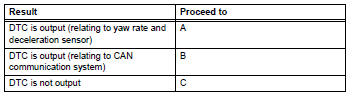

- Check yaw rate sensor installation
- Check that the yaw rate sensor has been installed correctly (see page bc-211).
Ok: the sensor is tightened to the specified torque.
The sensor is not tilted.

- Check wire harness (yaw rate sensor - battery and body ground)
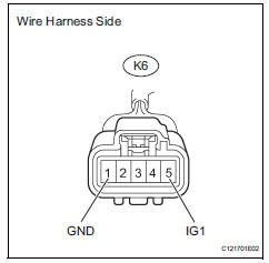
- Disconnect the k6 sensor connector.
- Measure the voltage of the wire harness side connector.
Standard voltage 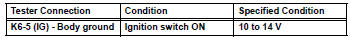
- Measure the resistance of the wire harness side connector.
Standard resistance 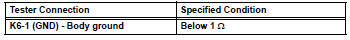

Replace yaw rate sensor
 Steering angle sensor circuit malfunction
Description
The steering sensor signal is sent to the skid control ecu via the can
communication system. When
there is a malfunction in the can communication system, it is detected by the
st ...
 Low battery positive voltage
Description
When there is an abnormality in the power supply circuit of the brake
actuator (skid control ecu), the skid
control ecu sets a dtc and the operation is prohibited by the fail-safe ...
Other materials:
Torque converter clutch solenoid performance (shift solenoid valve dsl)
Description
The ecm uses the signals from the throttle position sensor, air-flow meter,
turbine (input) speed sensor,
intermediate (counter) shaft speed sensor and crankshaft position sensor to
monitor the engagement
condition of the lock-up clutch.
Then the ecm compares the engagement ...
How to proceed with troubleshooting
Hint:
Perform troubleshooting in accordance with the following
flowchart.
*: Use the intelligent tester.
Vehicle brought to workshop
Inspect battery voltage
Standard voltage:
11 to 14 v
If the voltage is below 11 v, recharge or replace the battery
before proceeding.
Pr ...
Headlight relay circuit
Description
When the light control switch, located on the headlight dimmer switch, is
turned to the head position, the
head relay illuminates the headlights.
Wiring diagram
Inspection procedure
Perform active test by intelligent tester (headlight)
Connect the intelligent tester ( ...
